CHAPTER 6 The Thorax
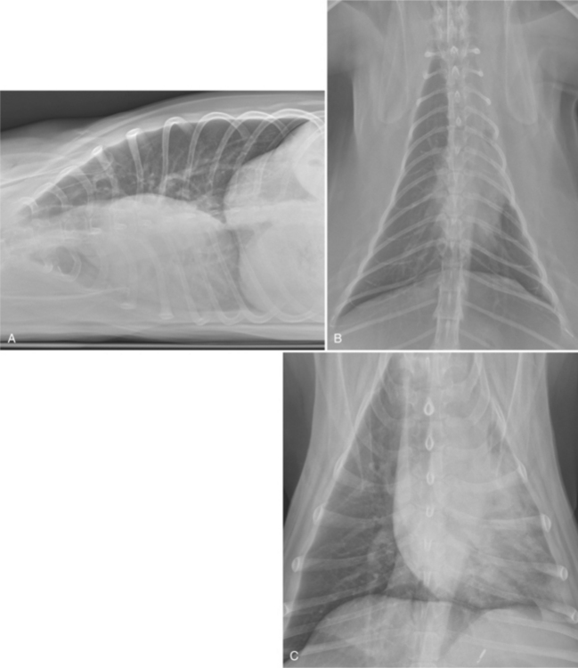
The thorax is suited well to radiographic imaging due to the inherent subject contrast afforded by the air-filled lungs. A vertical x-ray beam configuration should be used. The craniocaudal area imaged should extend from cranial to the manubrium to at least one to two vertebral body lengths caudal to the most dorsocaudal limit of the diaphragm (Figure 6-1). Dorsoventrally, the entire limits of the thoracic cavity should be covered by the primary x-ray beam.
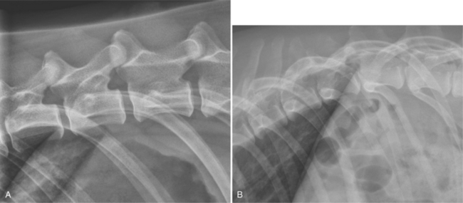
For lateral views, the goal should be to have the caudodorsal rib heads superimposed (Figure 6-2). This is usually accomplished by elevating the sternum with a small piece of non-radiopaque padding, for example, a foam pad placed under the axilla so that the sternum is in the same horizontal plane as the spine. In brachycephalic breeds or animals with a dorsoventrally compressed thorax, the sternum may actually need to be rotated toward the table rather than elevated to achieve superimposition of the rib heads. The forelimbs should be pulled cranially and the head and the neck extended slightly. The central axis of the x-ray beam (crosshairs) should be centered just caudal to the caudal aspect of the scapula in dogs and approximately 1 inch caudal to the caudal aspect of the scapula in cats.
The radiographic exposure should be made during peak inspiration to ensure optimal lung aeration (discussed in detail later). If possible, thoracic radiographs should be acquired without patient sedation, because sedation decreases lung aeration. The decreased aeration leads to increased pulmonary opacity, which reduces the radiographic conspicuity of pulmonary lesions and can be misinterpreted as an abnormal lung pattern. The thorax is a complex moving structure, so a radiograph acquired at peak inspiration can appear very different from a radiograph acquired later at peak expiration. A single radiograph is only a “snapshot in time” and might not reflect intrathoracic pathophysiology or disease accurately (Figure 6-3).
In a lateral thoracic radiograph with correct image blackness and contrast, both the skeletal structures, such as the thoracic spinous processes, and the pulmonary parenchymal structures in the narrowest part of the thorax, cranial to the heart, can be visualized (Figure 6-4). With film-screen systems, this is best achieved by using high kVp/low mAs exposure factors and a film-screen combination that has wide latitude (long scale of contrast). These imaging parameters result in extended grayscale and improved lesion conspicuity. The ability to see all structures within the image regardless of physical density and thickness is achieved much more easily with a digital imaging system, which is one of the many reasons why digital systems have grown rapidly in popularity.
The thoracic region has large differences in physical density and patient thickness, which challenges any imaging system. In addition, the thorax is undergoing continuous motion during radiographic exposure due to breathing and cardiac pulsations. A short exposure time is critical to avoiding motion artifact, which results in image blurring (Figure 6-5). Quality thoracic radiographs are best achieved by using an x-ray machine with a high mA output (so that exposure times can be minimized), an optimally configured digital imaging system, and a high kVp and low mAs technique.
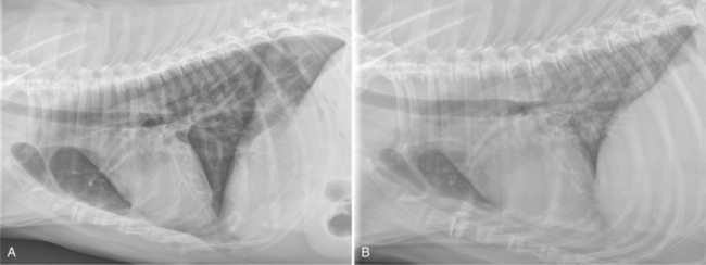
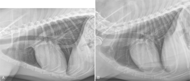
The reason for routinely acquiring both lateral views relates to the normal physiologic pulmonary atelectasis that occurs in the dependent lung. The dependent lung in a lateral view is less aerated, which can result in disease in that lung being obscured by the adjacent increased lung opacity. Acquiring both recumbent lateral views minimizes this problem (Figure 6-6).
Recumbency-associated atelectasis also occurs in VD and DV views, but not to the same extent as in lateral views. The absolute least amount of recumbency-associated atelectasis occurs with the subject in sternal recumbency, that is, the DV view.
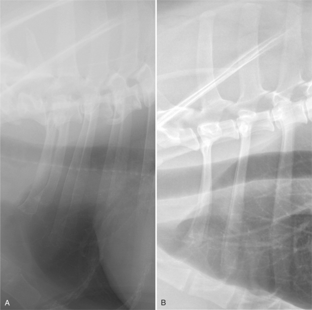
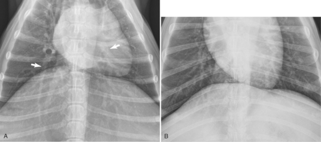
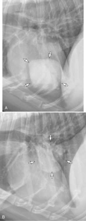
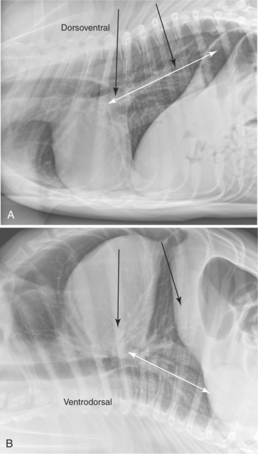
Although typically only either a VD view or a DV view is acquired, there are many situations in which obtaining both VD and DV views provides additional diagnostic information. Typically, dorsally located structures and pulmonary disease are more conspicuous in the DV view; conversely, ventrally located structures and pulmonary disease, including disease in the accessory lobe, are more conspicuous in the VD view (Figure 6-7).
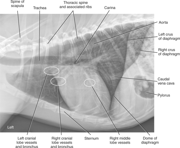
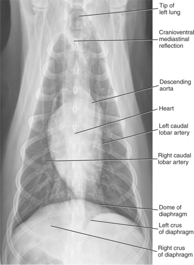
As with the abdomen, there are important anatomic differences between various views; understanding these variations enhances interpretation accuracy. Fairly consistent differences in appearance exist between left and right lateral views (and between DV and VD views) that, in most situations, readily distinguish them apart from each other. Figure 6-8 shows an overview of the major organs visible with thoracic radiography.
LEFT LATERAL VIEW
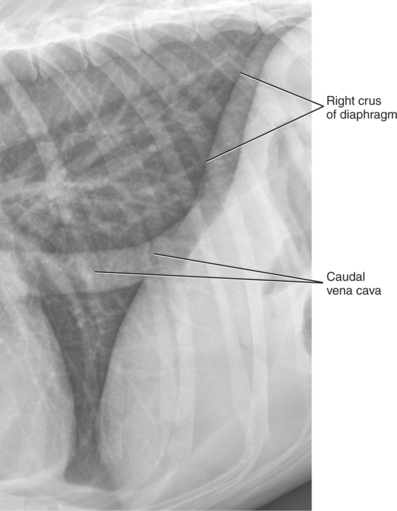
For a left lateral thoracic radiograph, the patient lies in left recumbency and the radiographic beam enters the right side of the thorax. Based on correct radiographic nomenclature, this radiograph projection should be termed a right-left view1 but this is usually abbreviated to just left lateral view (Figure 6-9). In the left lateral view, the diaphragmatic crura diverge dorsally, with the left crus typically being more cranial than the right crus. The left crus has no unique distinguishing features, but the right crus is identified by its confluence with the caudal vena cava, which passes through the caval hiatus in the right side of the diaphragm. The effect of recumbency on the relative position of the left and right diaphragmatic crus is fairly constant, but these relationships are not observed in every subject. Sometimes the right crus is more cranial in the left lateral view. The more cranial location of the left crus typically seen in left lateral radiographs is due both to pressure from abdominal organs pushing the left side of the diaphragm cranially and to decreased lung aeration in the dependent left lung (Figure 6-10).
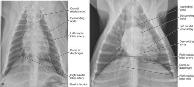
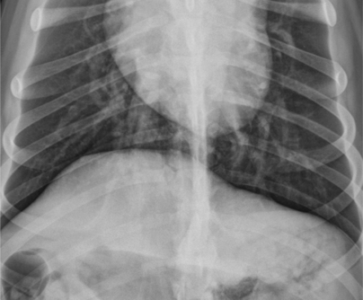
Figure 6-9 A, The same image as Figure 6-8, without labels. The radiographic exposure was made at optimal inspiration and the patient was positioned adequately. B, Left lateral radiograph of a 9-year-old mixed breed dog. The radiographic exposure was made at optimal inspiration and the patient was positioned adequately.
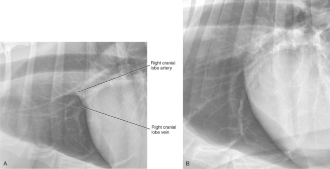
Pulmonary vessels are arranged as a pulmonary artery–pulmonary vein pair, with an interposed bronchus. In lateral views, the pulmonary artery is dorsal to the bronchus and the pulmonary vein is ventral. In VD or DV radiographs, pulmonary arteries are lateral to the bronchus, and pulmonary veins are medial. Careful examination of pulmonary artery–pulmonary vein pairs should be a routine step in the interpretation of thoracic radiographs, because a disparity in size is often the first radiographic sign of serious cardiovascular disease. The right cranial lobe pulmonary artery–pulmonary vein pair is typically the easiest to identify. This pulmonary artery–pulmonary vein pair is most conspicuous in the left lateral view where they are ventral to the left cranial lobe pulmonary vessels (see Figures 6-8 and 6-11). Pulmonary artery–pulmonary vein pairs should be evaluated in terms of their size, relative to each other, and their absolute size. The cranial lobe pulmonary vessels are usually equal in size to the width of the fourth rib at its most narrow point.2
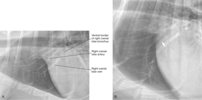
Interposed between any pulmonary artery–pulmonary vein pair is the corresponding bronchus. Importantly, a bronchus does not always occupy the entire space between a pulmonary artery and a pulmonary vein; therefore, the distance between the pulmonary artery and pulmonary vein should not be inferred as the size of the bronchus. Identification of a mineralized bronchial wall facilitates assessment of the absolute bronchus diameter, but mineralized bronchial walls are not visible in every patient (see Figure 6-11).
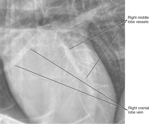
The right lung, being nondependent in a left lateral radiograph, is not affected by abdominal pressure and is better aerated than the dependent left lung. This optimizes visualization of normal pulmonary structures on the right side and the conspicuity of right-sided lesions. In a left lateral view, the vessels superimposed over the heart are typically the right middle lobar pulmonary artery and pulmonary vein. These vessels are commonly mistaken for coronary vessels. Pulmonary vessels are readily apparent radiographically because they are surrounded by air in lung. The air increases vessel conspicuity because it has a lower physical density and is much more radiolucent. The better the lung aeration, the more conspicuous pulmonary vessels and other parenchymal structures become. Coronary vessels are not visible without the administration of contrast medium or unless they are mineralized. Normally, coronary vessels are the same opacity as cardiac muscle and therefore silhouette with it. This results in border effacement and makes differentiation between heart and coronary vessel impossible (Figure 6-12).
RIGHT LATERAL VIEW
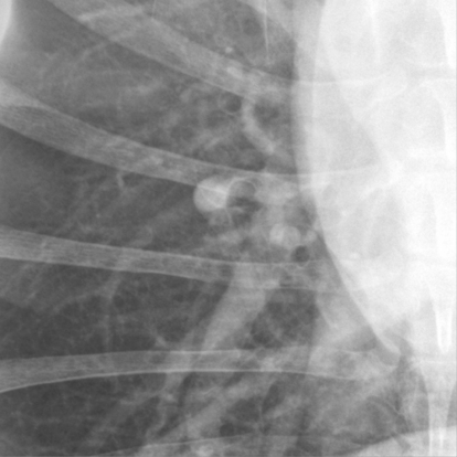
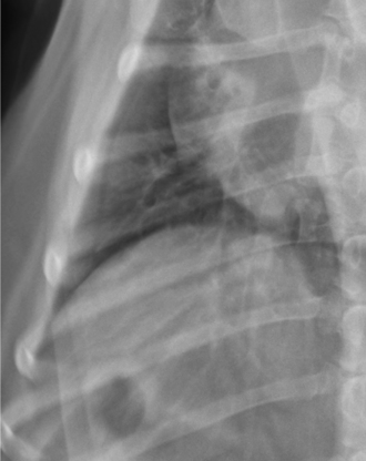
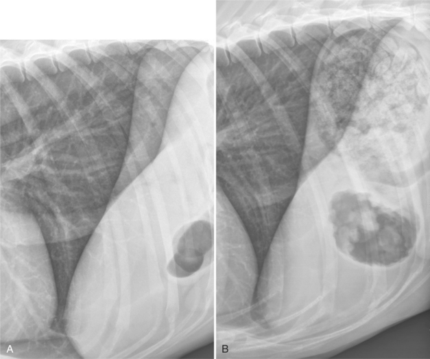
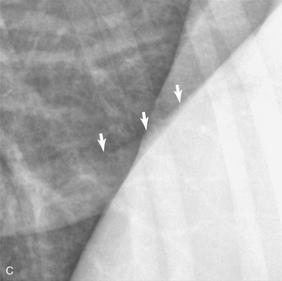
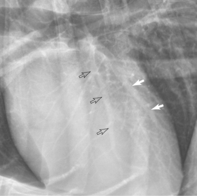
In the right lateral view, the patient lies in right recumbency and the x-ray beam enters the left side of the thorax. Similar to the left lateral view, based on correct radiographic nomenclature, this radiograph projection should be called a left-right view but this is usually abbreviated to just a right lateral view (Figure 6-13). In the right lateral view, the diaphragmatic crura are usually parallel (Figure 6-14). The right crus is typically more cranial than the left; however, as mentioned previously, this relationship does not hold in every normal dog. Opposite to the left lateral view, there is often more heart-to-sternal contact in the right lateral view. The right cranial lobe pulmonary artery and pulmonary vein are typically more dorsal than in the left lateral view and become superimposed on the left cranial pulmonary artery and pulmonary vein (Figure 6-15). This results in confusion and inaccuracy with regard to assessing the relative and absolute size of the cranial lobe pulmonary vessels. The more dorsal positioning of the right cranial lobe pulmonary vessels on the right lateral view is due to the effect of compression of the dependent hemithorax. As the dependent hemithorax is compressed, the lung is forced dorsally. Not only do normal structures in the dependent lung become displaced dorsally, but pulmonary lesions do as well. This occurs in both left and right lateral views. The dorsal shift of a right-sided pulmonary mass in the right lateral radiographs illustrates the magnitude of anatomic shift that occurs in the dependent lung (Figure 6-16).
Vessels to the caudal part of the left cranial lung lobe and cranioventral aspect of the left caudal lung lobe are usually visible overlying the caudal aspect of the cardiac silhouette (Figure 6-17). These too are sometimes incorrectly identified as coronary vessels.
DORSOVENTRAL VIEW
In the dorsoventral (DV) view, the patient is in sternal recumbency and the x-ray beam enters the patient dorsally and exits ventrally (Figure 6-18). The DV view can be difficult to position accurately, particularly in patients with hip osteoarthritis. Symmetrically positioning the forelimbs and ensuring that the head and neck are straight and lined up with the spinal axis increases positioning accuracy. The collimated field should be such that the entire thorax is imaged. The most common error occurs when the central beam is positioned too far caudally and a radiograph is obtained that includes too much of the abdomen and not enough of the cranial aspect of the thorax. In the DV view, the diaphragm has a domed appearance and extends more cranially than in the VD view as a result of abdominal pressure. This results in physical contact between the diaphragm and the cardiac silhouette, often leading to the apex of the cardiac silhouette being shifted to the left. The extent of cardiac shift to the left is a function of body mass, with more cardiac displacement occurring in larger dogs.3 The normal cardiac shifting to the left in the DV view is commonly misinterpreted as cardiomegaly. As in small dogs, cardiac shifting to the left in sternal recumbency is minimal in cats.4
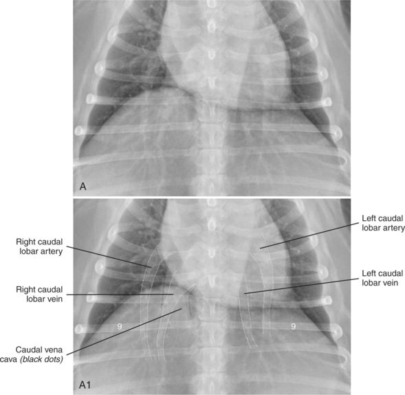
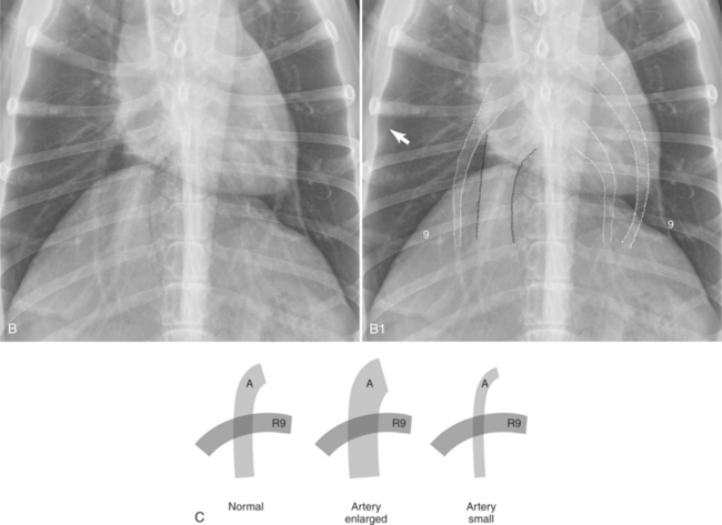
The caudal lobar pulmonary vessels are more conspicuous in the DV view than in the VD view (Figures 6-19 and 6-20). In sternal recumbency, the caudal lobe pulmonary vessels are more perpendicular to the oncoming x-ray beam, which leads to minimal distortion. In addition, in sternal recumbency there is little atelectasis of the caudal lung lobes; this optimal aeration results in increased vessel conspicuity. As noted previously, the left and right caudal lobar pulmonary arteries are located lateral to the bronchus, and the left and right caudal lobar pulmonary veins are medial to the bronchus (see Figure 6-19). Often, the right caudal lobar pulmonary vein is superimposed over the caudal vena cava, making assessment of both the right caudal lobar pulmonary vein and the caudal vena cava difficult (see Figure 6-19). Caudal lobar pulmonary vessels should taper gradually toward the periphery of the thorax. In the dog, the absolute size of the caudal lobar pulmonary artery and pulmonary vein should be approximately equal to the size of the ninth rib at the point at which the vessel intersects the rib (see Figure 6-19, C). The summation opacity created by the overlap can be used as a gauge of the relative size of the vessel.
VENTRODORSAL VIEW
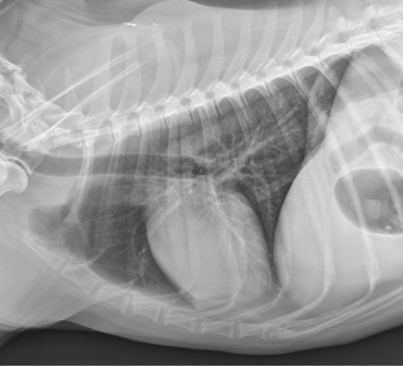
In the ventrodorsal (VD) view, the patient is in dorsal recumbency, and the x-ray beam enters the patient ventrally and exits dorsally. The VD view is often easier to position in patients with coxofemoral osteoarthritis because hindlimb extension is not required. Thin patients may benefit from padding under the spine to facilitate positioning. As with the DV view, it is important to position the forelimbs symmetrically and ensure that the neck is straight and the head is directed vertically. Asymmetrically positioning the forelimbs or bending the head and neck are common causes of thoracic malpositioning. The VD view should not be attempted in patients with obvious cardiopulmonary compromise as decompensation can result due to patient stress. In the VD view, the diaphragmatic crura have a convex appearance and the dome of the diaphragm is usually more caudal, because there is less abdominal pressure on the dome of the diaphragm when compared with a patient in sternal recumbency. This usually results in the presence of aerated lung between the caudal aspect of the heart and the diaphragm, thus allowing better visualization of the accessory lung lobe3 (Figures 6-21 and 6-22). The caudal lobe pulmonary arteries and pulmonary veins are less conspicuous in the VD view than in the DV view because they are at a steep angle with respect to the primary x-ray beam and are therefore distorted. There also is more compression atelectasis of the caudal lobes with the subject in dorsal recumbency, which contributes to decreased vessel conspicuity in the caudal lung lobes (Figure 6-23).
The cardiac silhouette is usually more elongated and narrow in the VD view compared with the DV view. It is also less subject to displacement from diaphragmatic contact, leading to the heart typically being more centrally located within the thorax.3
The decision to use anesthesia or sedation for thoracic radiography depends on many factors, including local radiation safety regulations. When general anesthesia is used, modest positive pressure ventilation should be used during the radiographic procedure to achieve optimal lung aeration. Anesthesia should be induced with the patient in sternal recumbency, and the patient should remain in sternal recumbency until lateral radiographs are made. The time between anesthesia induction and radiography should be minimized.
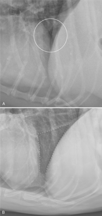
The interpretation of thoracic radiographs made after prolonged lateral recumbency or anesthesia is complicated by pulmonary atelectasis and a secondary mediastinal shift. The lack of support from the inadequately aerated lung results in a shift of mediastinal structures toward the side with atelectasis (see Figure 6-6). With respect to lateral views, the overall adequacy of lung aeration is best assessed by evaluating the size of the triangular region between the caudal aspect of the heart, the ventral aspect of the caudal vena cava, and the dome of the diaphragm. The larger the volume of this triangular region is, the better the overall pulmonary aeration (Figure 6-24).