CHAPTER 3 The Spine
Survey radiography of the spine typically involves acquisition of lateral and ventrodorsal projections; thus this chapter emphasizes these projections. To facilitate accurate radiographic interpretation, patients for spinal radiography should be sedated or anesthetized to optimize positioning. Optimal positioning for spinal radiographs is critical. The anatomic complexity of the spine can easily lead to an incorrect interpretation if positioning errors exist.
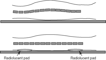
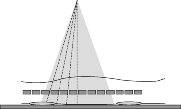
For lateral views, it is critical that the midsagittal plane of the patient, and thus of the spine, be parallel to the x-ray table top. This may require intentionally elevating the sternum slightly so that the spine and sternum are in the same plane. In addition, even if the sternum is elevated, the patient cannot simply be allowed to lie on the x-ray table for the lateral projection. Unless spinal regions that sag are elevated with non-radiopaque sponges, the natural undulation of the vertebrae will lead to distortion (Figure 3-1).
Another important fact with regard to positioning for lateral spinal radiographs is that the divergent nature of the primary x-ray beam will lead to only a few intervertebral disc spaces being projected at a size that is representative of the true size. Beam divergence results in angulation of the x-ray beam with respect to the disc spaces at the edge of the field, and this creates a false appearance of disc space narrowing (Figure 3-2). To compensate for this, multiple lateral projections of any spinal region are needed, with the center of the x-ray beam located at multiple locations, that is, the center of the x-ray beam at C3 and C6 for lateral cervical spinal series, and the center of the x-ray beam at T5, T9, T13, L3, and L7 for thoracolumbar series.
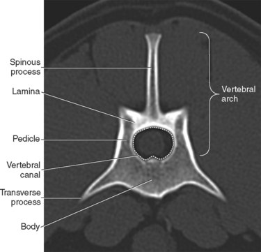
Although size and shape of vertebrae along the spine vary considerably, each vertebra has a set of core components that this chapter refers to frequently. The vertebral body forms the bulk of the mass of each vertebra. Transverse processes extend laterally from the body. Dorsal extensions from each side of the body, the pedicles, form the lateral boundaries of the vertebral canal. The pedicles are joined dorsally by a bony shelf, the lamina, which forms the dorsal limit of the vertebral canal. A spinous process extends dorsally from the lamina. The pedicles, lamina, and spinous process are collectively termed the vertebral arch (Figure 3-3). The vertebral arch can also be referred to as the neural arch, but this chapter uses the term vertebral arch throughout.
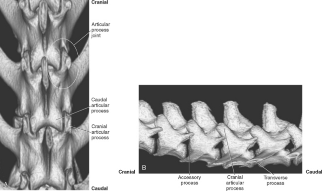
Vertebral bodies articulate via the intervertebral disc, a cartilaginous and fibrous structure that allows some motion and provides cushion. The disc, being non-mineralized normally, is of soft tissue opacity and creates a relatively radiolucent region between vertebrae. Vertebrae also articulate dorsally at the articular process joints. There are four articular processes on most vertebrae: left and right cranial articular processes and left and right caudal articular processes. The articular processes are located on the vertebral arch, at the junction of the pedicles and lamina. A cranial articular process joins with a caudal articular process from the vertebra located immediately cranially to form an articular process joint (Figure 3-4). The cranial articular process is lateral to the caudal articular process (see Figure 3-4). The face, or facet, of the articular process is the cartilage-covered articular surface of the articular process; the term facet should not be used to encompass the entire articular process or to describe the joint. The articular process joints are synovial diarthrodial joints.
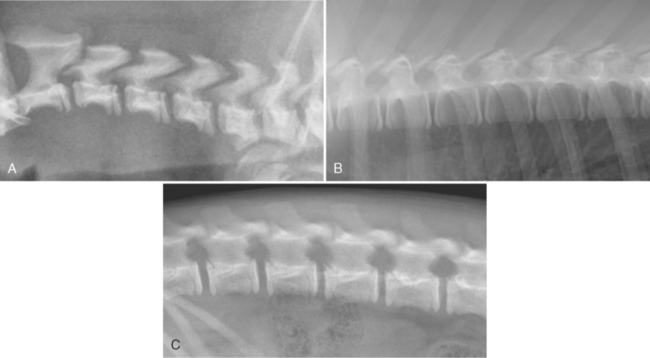
Except for C1 and C2, cervical, thoracic, and lumbar vertebrae have three primary centers of ossification: one for the centrum, or body, and one for each vertebral arch.1 The centrum has a growth plate, or physis, and adjacent secondary centers of ossification, the epiphyses, on the cranial and caudal ends. Vertebral physes, being cartilaginous, are visible radiographically as a radiolucent region between the body and the epiphysis. When vertebral physes are open, the ventral aspect of the vertebra has an irregular, jagged margin (Figure 3-5).
CERVICAL SPINE
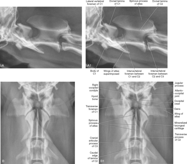
There are seven cervical vertebrae, and the variation in size and shape of individual cervical vertebrae is greater than in any other spinal region. The first cervical vertebra, termed the atlas, articulates with the occipital condyles at the atlanto-occipital articulation. There is no intervertebral disc between the occipital condyles and the atlas. The atlanto-occipital articulation provides for flexion and extension but not lateral or rotary movement; thus, this joint has been referred to as the “yes” joint. There are no typical cranial and caudal articular processes on the atlas; instead there are articular fovea cranially and caudally to accommodate articulation with the occipital condyles and centrum 1 of the axis, respectively. The atlas also does not possess a spinous process, and the body is abbreviated compared with other cervical vertebrae.2 The transverse processes of the atlas are large and are termed wings3 (Figure 3-6). The atlas has two foramina on each side, the left and right lateral vertebral foramina, which are located in the craniodorsal part of the vertebral arch (see Figure 3-6, A1), and the left and right transverse foramina, located in the wings (see Figure 3-6, B1). The vertebral artery and vein pass through the transverse and lateral vertebral foramina, and the first cervical spinal nerve exits through the lateral vertebral foramen.
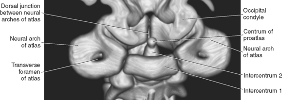
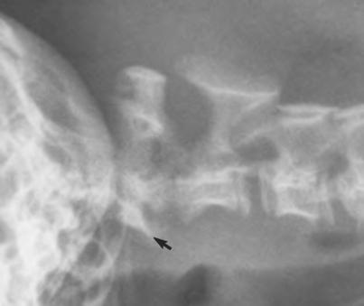
The atlas arises from three centers of ossification, a pair of vertebral arches that become the vertebral arch, and intercentrum 1 that becomes the body4,5, (Figures 3-7 and 3-8). The vertebral arches fuse dorsally shortly after 100 days, and the body fuses with the vertebral arches slightly later, in the range of 110 to120 days.2 Intercentrum 1 is rarely seen radiographically as a separate structure due to its overlap with the ventral aspect of the adjacent vertebral arches of the atlas, but occasionally intercentrum 1 may appear as a fragment, especially when the patient is positioned slightly obliquely (see Figure 3-8).
The second cervical vertebra, the axis, is the largest cervical vertebra. Its most conspicuous feature is the large spinous process, the cranial portion of which overlaps the lamina of the atlas (see Figure 3-6, A). As at the atlanto-occipital junction, there is no intervertebral disc between C1 and C2. Given the unique articulation between C1 and C2, there are no cranial articular processes on C2; however, caudal articular processes are present and they form the articular process joint at C2-C3. The lack of cranial articular processes on C2 allows an unobstructed view of the intervertebral foramen at C1-C2 in lateral radiographs (see Figure 3-6, A and A1). As discussed on pg. 45, this is contrary to sites more caudal in the cervical spine where the articular processes are superimposed on intervertebral foramina in lateral radiographs.
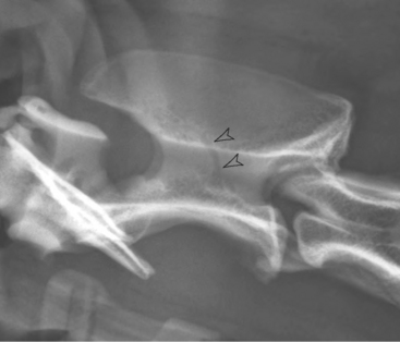
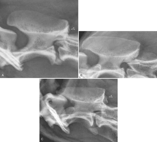
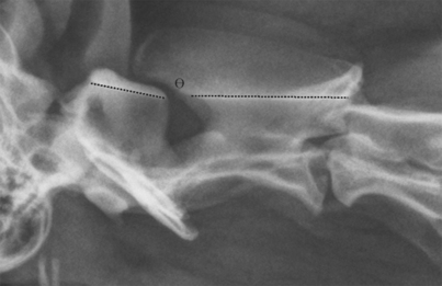
Another unique feature of the axis is the dens, an oblong protuberance that extends into the ventral aspect of the vertebral canal of C1. The dens is difficult to identify in lateral radiographs due to its superimposition with portions of C1, but the dens can often be identified in the ventrodorsal view (see Figure 3-6, B and B1). If visualization of the dens is a priority, a ventrodorsal view with the patient intentionally obliqued slightly to the left or right can be made; often the dens is more conspicuous in this slightly obliqued image. Normally, there is literally no flexion possible at the atlantoaxial joint due to the stabilization provided by the apical ligament of the dens, the transverse atlantal ligament, and dorsal atlantoaxial ligament. The apical ligament of the dens has three pillars that extend cranially: the middle one runs to the ventral aspect of the foramen magnum, and the two lateral, more robust pillars attach to the occipital bone. The transverse atlantal ligament is strong and connects one side of the ventral arch of the atlas to the other by crossing over the dens, holding it against the body of the atlas.6 Lateral or rotary movement is possible at the atlantoaxial joint. Because of the limited flexion and extension possible at the atlantoaxial joint, it has been referred to as the “no” joint. Occasionally, due to either a congenital malformation or trauma (or both), there is instability at the atlantoaxial joint with increased flexion. A good method to assess the alignment of the atlantoaxial joint is to compare the orientation of the dorsal lamina of the atlas with respect to the dorsal lamina of the axis (Figure 3-9). Under normal circumstances, these laminae should align in a nearly linear fashion (see Figure 3-9). The amount of overlap of the spinous process of C2 with the dorsal lamina of C1 will vary between subjects, as will the distance between the lamina of C1 and the spinous process of C2, making these relationships of little value for assessing atlantoaxial alignment. However, the parallel, or linear, orientation of the lamina of C1 and C2 is relatively constant and is a good landmark for assessing the normality of the C1-C2 alignment (Figure 3-10).
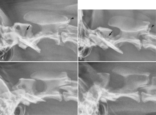
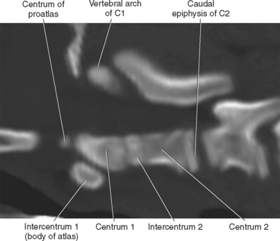
The axis arises from seven centers of ossification: two vertebral arches, centrum 2, caudal epiphysis, intercentrum 2, centrum 1, and centrum of proatlas (Figure 3-11). Centrum 1 and the centrum of the proatlas form the dens; the centrum of the proatlas is embryologically a part of the atlas4,5 (see Figure 3-7). The centrum of the proatlas fuses with centrum 1 at approximately 100 to 110 days, intercentrum 2 fuses with centrum 1 and centrum 2 in the range of 115 to 150 days, and the caudal epiphysis fuses with the body of C2 in the range of 220 to 400 days.2
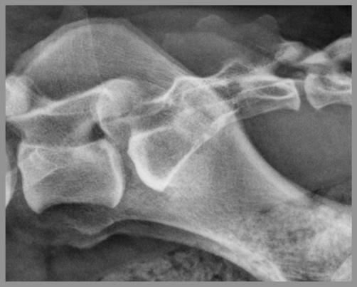
Occasionally a large conspicuous linear radiolucent region will be visible in the vertebral arch of C2 in mature dogs; this is due to a vascular channel and should not be confused with a fracture or a destructive process (Figure 3-12). In addition, the trabecular pattern in parts of the vertebral arch of C2 is often very heterogeneous, with coarse round radiolucent regions; this appearance should also not be confused with a destructive process, such as lysis due to a reticuloendothelial tumor (Figure 3-13). The dogs in Figure 3-13 are all elderly and, although not documented, this coarse trabecular pattern could be due to a degree of geriatric osteopenia.