CHAPTER 1 Introduction
HOW TO USE THIS ATLAS
As described in the Preface, a radiographic atlas is intended to help decide whether any given radiographic appearance is normal or abnormal. Determining normal from abnormal is one of the most difficult, if not the most difficult, part of the radiographic interpretive process. No atlas will be able to provide a clear answer to the “Is it normal or abnormal?” question in every circumstance, but the material in this book can help guide the decision-making process.
The best way to use this atlas is to spend some time with it, and get to know it. Of course, labeled images are provided—every atlas needs these. But, contrary to a pure picture atlas, some of the most valuable information in this atlas is contained within the text. Being familiar with the text, which has been kept brief and focused, and noting how important principles have been augmented with illustrative examples can help bolster a basis for interpretation that extends beyond simple structure identification.
WHAT IS NORMAL?
Many dogs and cats have congenital, developmental, and degenerative changes that are insignificant clinically but apparent radiographically. These disorders, in many subjects, are manifestations of selective breeding over many decades. Demonstrating a selection of these common variations simply acknowledges the existence of such variations and does not necessarily endorse such breeding practices. This book demonstrates the morphologic diversity currently present in domestic canine and feline companions that has come to be commonly accepted as normal.
RADIOGRAPHIC TERMINOLOGY
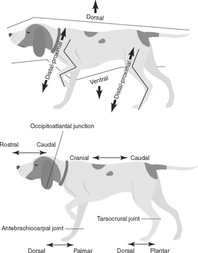
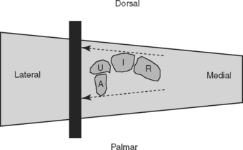
This book uses the standard method for naming radiographic projections approved by the American College of Veterinary Radiology (1). In general, this naming method is based on anatomic directional terms (as defined by the Nomina Anatomica Veterinaria) combined with the point-of-entrance to point-of-exit of the primary x-ray beam. Figure 1-1 diagrams the accepted anatomic directional terms. Several important concepts are commonly violated, leading to improper radiographic identification. In summary, these are:


VIEWING IMAGES
When all radiographic images were made using film-screen systems, a method for consistently hanging the radiographs on a viewbox was developed. Hanging radiographs the same way for every subject reduces variation, and the mind becomes more familiar with the way a certain body part should appear in an image. The basic aspects of that radiograph-hanging system are:


Although these principles were developed with relevance to how a radiograph should be displayed on a viewbox, they have carried over to the digital age and are used to direct how the digital image should be displayed on a monitor or in print.
STANDARD PROJECTIONS
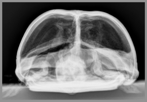
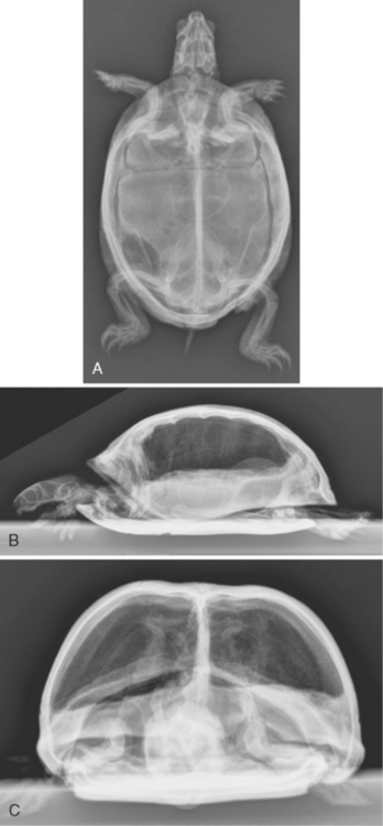
Most body parts being radiographed are usually subjected to multiple views at different beam angles. Most commonly, this involves views made at 90° to each other, termed orthogonal views. Table 1-1 lists the most common orthogonal views for the major body parts. It is critical to routinely make standard orthogonal views; the complexity of various anatomic parts is simplified by the repetitive aspect of looking at the same radiographic projections over and over. When an object is viewed in an unfamiliar orientation, relevant anatomy becomes less recognizable (Figure 1-2).
Table 1-1 Common Orthogonal Views for Major Body Parts
Body Part | View | Orthogonal View |
---|---|---|
Skull | Lateral | Ventrodorsal or dorsoventral |
Spine | Lateral | Ventrodorsal |
Thorax | Lateral | Ventrodorsal or dorsoventral |
Abdomen | Lateral | Ventrodorsal |
Pelvis | Lateral | Ventrodorsal |
Brachium, antebrachium, thigh, crus | Lateral | Craniocaudal or caudocranial |
Manus | Lateral | Dorsopalmar |
Pes | Lateral | Dorsoplantar |

Figure 1-2 Dorsoventral (A), lateral (B), and rostocaudal (C) radiographs of a box turtle. The fact that the subject is a turtle is easily recognizable in A and B, which are orthogonal radiographs. That the subject is a turtle is less obvious in C, which is also an orthogonal view with respect to both A and B. However, this view is acquired much less frequently, making it unfamiliar with most interpreters. In addition, the fact that there are eggs in the coelom would not be determined if only view C is being consulted. This example emphasizes the need for at least two orthogonal views of any body part being radiographed and the need to use the same standardized views in every subject.
OBLIQUE PROJECTIONS
For anatomically complex regions, such as the carpus, tarsus, manus, and pes, two orthogonal radiographic views are not adequate to assess all aspects of the structures. There is too much superimposition in two orthogonal views for all surfaces to be assessed completely, and important lesions can be missed. The objective of radiographing complex structures using multiple views is to project as many surfaces or edges in the most unobstructed manner possible. The internal structure of complex regions can sometimes be assessed, even with overlapping, because of the penetrating nature of x-rays. However, the assessment of a complex structure is going to be most accurate when the structure, or at least its edge, is projected in an unobstructed manner.
The best solution to the problem of superimposition is to use a tomographic imaging modality. Tomographic imaging modalities display images in slices, thus avoiding the problem of superimposition completely. Ultrasound, computed tomography, and magnetic resonance imaging are all tomographic imaging modalities. Of course, these modalities are not available for daily use in most practices, and thus the use of oblique radiographs is another method to solve problems associated with superimposition of structures.
For oblique radiography, projections in addition to the standard orthogonal projections are acquired; the angle of the primary x-ray beam with respect to the part being radiographed is somewhere between the angles used for the standard orthogonal projections. Typically, this angle is approximately 45 degrees, but other angles can be used depending on the circumstances. The concept of oblique radiographic views will be illustrated with a few examples. The radiographic naming concept previously described is crucial to understanding this information. That is, radiographic views are named according to the direction of the primary x-ray beam, from point-of-entrance to point-of-exit.
This chapter presents examples of oblique radiography based on radiography of the canine tarsal and canine carpal joints.*
Dorsopalmar or Dorsoplantar View
The dorsopalmar or dorsoplantar view is one of the two basic orthogonal radiographic views of extremities. It is made when the x-ray beam strikes the dorsal (front) surface of a limb perpendicularly with the cassette or imaging plate behind the limb, perpendicular to the primary x-ray beam. The correct name of this view depends on whether the limb is a forelimb or hindlimb, and whether the central portion of the primary x-ray beam is proximal or distal to the antebrachiocarpal or tarsocrural joints (Table 1-2).
Table 1-2 Correct Names for Radiographic Projections of a Limb Where the X-Ray Beam Strikes the Front Surface of the Limb and the Cassette or Imaging Plate Is Directly Behind the Limb
Correct Name of View | Orientation |
---|---|
Dorsopalmar | Primary x-ray beam strikes front surface of forelimb at antebrachiocarpal joint or distal. Cassette or imaging plate is perpendicular to primary x-ray beam. |
Dorsoplantar | Primary x-ray beam strikes front surface of hindlimb at tarsocrural joint or distal. Cassette or imaging plate is perpendicular to primary x-ray beam. |
Craniocaudal | Primary x-ray beam strikes front surface of forelimb or hindlimb proximal to antebrachiocarpal joint or tarsocrural joint. Cassette or imaging plate is perpendicular to primary x-ray beam. |
In a dorsopalmar view of a carpus, for example, the x-ray beam strikes the dorsal surface of the carpus with the image plate behind the carpus oriented perpendicular to the primary x-ray beam (Figure 1-3). In this geometric arrangement, only the medial and lateral aspects of the structure of interest can be visualized in an unobstructed manner (see Figures 1-3 and 1-4). This does not mean that only the edges of the structure can be evaluated; the infrastructure can be assessed but the lateral and medial surfaces are primarily where a periosteal reaction or cortical erosion can be identified.

Figure 1-3 The proximal row of carpal bones is shown as though the carpus was sliced transversely at that level. The x-ray beam strikes the carpal bones from the front. As can be seen, the only surfaces that can be projected in an unobstructed fashion are the medial side of the radial carpal bone (R) and the lateral side of the ulnar carpal bone (U); dotted arrows indicate these surfaces. These are the only surfaces that can be evaluated for surface lesions, such as periosteal reaction or cortical lysis. Other surfaces will be superimposed on another structure and cannot be assessed accurately.

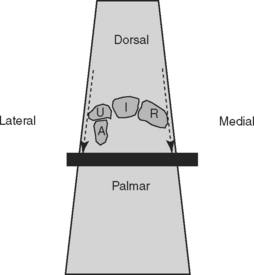
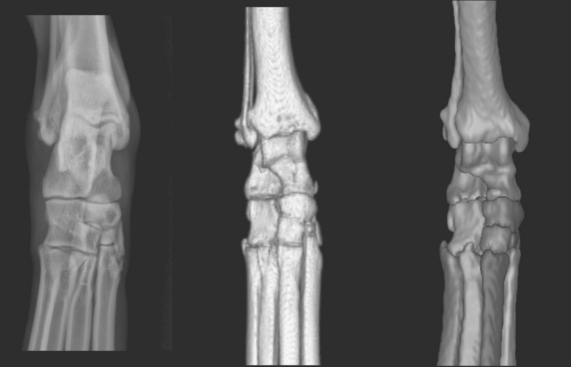
Figure 1-4 The left panel shows a dorsoplantar radiograph of a canine tarsus. The middle panel shows a threedimensional rendering of a normal right canine tarsus as seen from the perspective of the x-ray beam when making a dorsoplantar radiograph. The right panel shows a threedimensional rendering of a normal right canine tarsus, also as seen from the perspective of the x-ray beam when making a dorsoplantar radiograph, but where each bone has been colorized (see Color Plate 1). The colorized version makes it easier to comprehend the extent of overlap. Note in the radiograph how the only aspects of the tarsal bones that are projected in an unobstructed fashion where the surface can be evaluated are the medial and lateral aspects of the tarsus.
Lateral View
The complementary orthogonal view to the dorsopalmar (or dorsoplantar) view of the extremities is the lateral view. It is made when the x-ray beam strikes the side surface of a limb with the cassette or imaging plate on the opposite side of the limb, perpendicular to the primary x-ray beam (Figure 1-5). These views are most often referred to as lateral views, although lateromedial or mediolateral is more correct depending on whether the lateral or medial aspect of the limb, respectively, is struck by the primary x-ray beam.

Figure 1-5 The proximal row of carpal bones is shown as if the carpus was sliced transversely at that level. The x-ray beam strikes the structure from the medial side, in this instance a mediolateral view. As can be seen, the only surfaces that will be projected in an unobstructed fashion are the dorsal surface of the intermediate carpal bone (I) and the palmar side of the accessory carpal bone (A); dotted arrows indicate these surfaces. These surfaces are the only surfaces that can be evaluated for surface lesions, such as periosteal reaction or cortical lysis.

Stay updated, free articles. Join our Telegram channel

Full access? Get Clinical Tree

