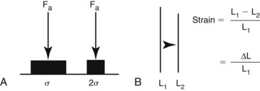
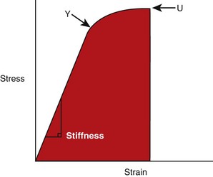
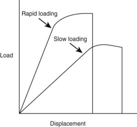
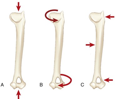
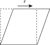
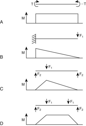
Chapter 41 Stress and strain: Stress, like pressure, is a local force expressed in units of force per unit area. The SI unit of force is the Newton, and force is often expressed as N/m2. Strain is a local deformation expressed as units of length per length, and usually expressed as a percentage (Figure 41-1). Because a 1 mm fracture gap displacement is obviously more significant in a 10 mm rat (10%) femur than in a 300-mm dog femur (0.3%), strain provides a clinically useful scaled measure of displacement. Strength and stiffness: Strength denotes the ultimate load a material can withstand before catastrophic failure. Stiffness refers to the rate at which a material deforms when a load is applied. A stress/strain curve (Figure 41-2), which applies to materials and is called a load/displacement curve when referring to structures, best illustrates these properties. The slope of the ascending linear portion of the curve represents elastic modulus or stiffness. The steeper the slope of this portion of the curve, the stiffer is the material. The strain (or displacement) in this area of the curve is considered elastic because the material can return to its prestrained state. Y, known as the yield point, marks where the curve becomes nonlinear. At this point, the strain exceeds the material’s ability to recover, rendering the material permanently deformed. This permanent deformation, called plastic (versus elastic) deformation, results from breaking of covalent bonds at a molecular level. The ultimate failure point, U, on the curve, indicates where the material can withstand no more strain and fails. The area under the curve, also considered toughness, represents the total energy absorbed during the loading process. As was discussed earlier, cortical bone is both viscoelastic and anisotropic. As a viscoelastic material, the more rapidly the bone is stressed, the stiffer it becomes (steeper elastic phase of the stress/strain curve). Although it is not yet fully understood, the structural reason for this behavior is likely related to the interactions of fluids within the calcified bone matrix. Rapidly loaded bone also stores more energy (area under the curve). Unfortunately, once a rapidly loaded bone reaches the failure point (U), releasing more energy, more complex fractures and greater soft tissue damage result. Conversely, fractures that occur at low loading rates tend to be simple fractures with less soft tissue damage because less energy was stored during loading and released at failure (Figure 41-3). Because cancellous bone typically has porosity (the ratio of the volume of open space to the total bone volume) of between 75% and 95% versus 5% to 10% for cortical bone, it comes as no surprise that the material properties of cancellous and cortical bone differ markedly. In general, cancellous bone is weaker and more compliant than cortical bone. The stress/strain curve for cancellous bone shows an initially shorter elastic segment (lower yield point) and has a lower stiffness—less than 10% that of cortical bone. Upon reaching the yield point, however, cancellous bone has a very long plastic phase. This phase represents the progressive fracture and collapse of the cancellous trabecula. Once trabecular debris fills the marrow spaces and the cancellous bone compacts, the curve once again turns upward, illustrating the resulting increased stiffness. This prolonged plastic deformation period explains why the total energy absorbed by cancellous bone under compression can exceed that of cortical bone (Figure 41-4). Bones are subjected to many and combined forces during normal function. When the magnitude of the sum of these forces exceeds the ultimate strength of the bone, a fracture occurs. It is conceptually useful to identify these forces by their orientation to the loaded bone (Figure 41-5). Axial forces act parallel to the long axis of the bone. Further divided, tensile forces tend to lengthen the bone and compressive forces tend to shorten it uniformly. Shear forces are difficult to conceptualize with respect to an entire bone but are common within bone. Shear forces act parallel or tangential to the face of a material (Figure 41-6). Bending forces act to make the bone convex on one side and concave on the opposite side. Bending forces are often referred to as moments. A moment is a tendency for a force to twist or rotate an object and is expressed in units of torque. Bending loads may be applied in different ways. Pure bending results from applying an equal and opposite bending moment at each end of the bone. This causes a uniform bending moment across the length of the bone (Figure 41-7, A). As such, a fracture could occur at any point along the bone. This bending situation rarely occurs in the appendicular skeleton. Cantilever bending results from fixing the bone at one end and applying a transverse load at the other. This causes a bending moment that is highest at the fixation point, and from there it linearly decreases (Figure 41-7, B). For example, when a soccer player kicks a ball, the proximal tibia becomes the fixation point, and the transverse load is applied to the distal tibia through the ankle joint. In cantilever bending, the fracture will occur at the site of fixation. Three-point bending results from an equal load applied at each end and an opposite load applied at some point between the ends. This causes a bending moment that is highest at the site of load application and decreases linearly with distance from that site (Figure 41-7, C). In this case, the soccer player, standing on the field, gets kicked in the tibia by another player. In three-point bending, the fracture will occur at the site of load application. Four-point bending results from loads applied at each end and two opposite loads applied at points between the ends. This causes a bending moment that increases from one end to the first inner load, is constant to the next inner load, and decreases to the other end load (Figure 41-7, D). This loading condition is rare in the appendicular skeleton as well.
Fracture Biology and Biomechanics
Biomechanical Concepts
Cortical Bone Material Properties
Cancellous Bone Material Properties
Fracture Biomechanics
< div class='tao-gold-member'>
![]()
Stay updated, free articles. Join our Telegram channel


Full access? Get Clinical Tree


