Chapter 1 Endoscopic Instrumentation and Documentation for Flexible and Rigid Endoscopy
Endoscope System
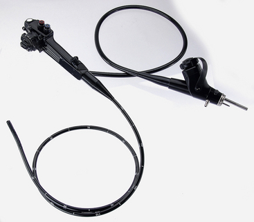
The endoscopy imaging chain includes a light source, light-transmitting cable, endoscope, camera, and monitor (Figure 1-1). Each component is essential, and the resulting endoscopic image can only be as good as the weakest link in that chain. On many flexible endoscopes, the light-transmitting cable is permanently attached to the endoscope and has a connector that plugs directly into the light source (Figure 1-2).
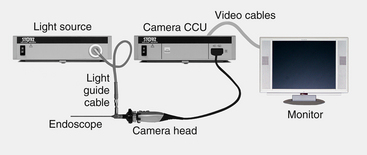
Figure 1-1 Endoscopy imaging chain begins with a light source and ends with a monitor.
(Photo courtesy of Karl Storz GmbH & Co. KG, Tuttlingen, Germany.)
Flexible Endoscopes
The ability to view the endoscopic image on a video monitor and record or print this information is not unique to video endoscopes. Indirect video endoscopy can be accomplished by attaching an endoscopic CCD video camera to the eyepiece of a fiberscope or rigid endoscope (see “Endoscopic Imaging Systems” later in this chapter, Figure 1-25). Although true video endoscopes are preferred for superior visualization in gastrointestinal endoscopy, CCD video cameras are still necessary for use with rigid endoscopes (e.g., laparoscopes and arthroscopes), as well as smaller diameter fiberscopes. Fortunately, the combination of a good quality video camera and fiberoptic endoscope can provide very good images. The smallest flexible video endoscopes currently available for medical use are approximately 5 or 6 mm in outer diameter, depending on chip technology and mechanical functions, such as channel size and deflection capability. Until the technologic limitations on the miniaturization of CCD chips are overcome, the production of very small diameter video endoscopes is not feasible.
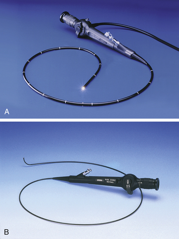
Although fiberscopes are less expensive than video endoscopes, the cost of the latter has recently come down and the image quality of video endoscopes is far superior to that of fiberscopes (Figure 1-3). Because the image produced by a video endoscope is not fiberoptic, it will never contain the honeycomb pattern or broken fibers seen as black dots in a fiberoptic image. The features of fiberscopes and video endoscopes are compared in Table 1-1.
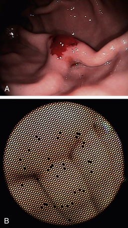
Table 1-1 Features of Fiberscopes versus Video Endoscopes
| Feature | Fiberscope | Video endoscope |
|---|---|---|
| Image quality | Good | Excellent |
| Broken fibers seen as “black dots” | Likely over time | N/A (image is electronic, not fiberoptic) |
| Cost | Moderate | High |
| Diameters available | Wide range available | Smaller diameters not available∗ |
| Video capability | Requires attachable charge coupled device (CCD) camera | Integral |
∗ Due to limitations on chip miniaturization.
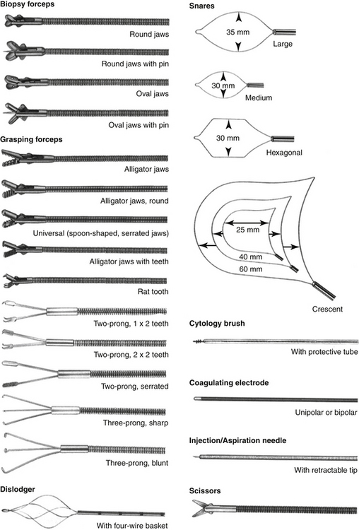
Flexible endoscopes are available in diameters ranging from 14 mm to less than 1 mm. Most flexible scopes greater than 2 mm in diameter are equipped with an accessory channel and a deflectable tip. The working channel is the section of the endoscope through which ancillary instruments like biopsy forceps (Figure 1-4) are advanced into the patient. Because of their versatility, the most popular endoscopes in small animal practice are gastroscopes, which have four-way tip deflection. The tip’s two-plane deflection capability (i.e., up, down, left, and right) is crucial to the successful navigation of the gastrointestinal tract, particularly in the most challenging maneuvers through the pylorus and ileocolic orifice. A gastroscope less than 9 mm in diameter and at least 130 cm in length is suitable for both upper and lower gastrointestinal endoscopy in most cats and dogs, as well as tracheobronchoscopy in medium and large size dogs.
Because most gastroscopes have an outer diameter of 7.8 mm or greater, they cannot be used in smaller dogs and cats for such procedures as bronchoscopy, rhinoscopy, and urethrocystoscopy. Consequently, the second and third most popular flexible endoscopes in small animal practice are small-diameter fiberscopes that are used primarily for endoscopy of the airways and urinary tract (Figure 1-5). These smaller diameter fiberscopes, ranging from 2 mm to 6 mm, generally have limited tip deflection capability (one-way or two-way) and smaller working channels.
Basic Construction and Handling
A flexible endoscope has three major sections (Figure 1-6): the insertion tube, the handpiece, and the umbilical cord. Construction of the insertion tube is the most complex and technically challenging aspect of gastroscope design because this portion of the instrument contains fiberoptic bundles; channels for suction, irrigation, and insufflation; four deflection cables; and several layers of protective materials along the entire length of the tube. All of these components must be contained within an insertion tube that has the smallest possible diameter, largest possible accessory channel, and maximal tip deflection capabilities. Because of the complexity of construction and the fragile nature of some components, damage to the insertion tube is the most expensive type of repair performed on gastroscopes. Most insertion tube damage can be prevented by observing the following:
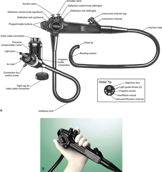
A close-up inspection of the distal tip of an insertion tube shows the cross-sectional location of several of the internal structures (Figure 1-6, see “Distal Tip” box). The insufflation channel allows room air to be blown into the gastrointestinal tract, distending the viscus and enabling clearer and more thorough examination of the mucosa. The water jet exiting the irrigation nozzle is directed over the distal objective lens to remove debris and mucus when necessary. The accessory channel is used for suction of air and fluids, as well as the passage of flexible instruments into the patient (see Figure 1-4). Because of this fact, the effectiveness of suction is greatly reduced when an instrument is inside the channel.
The handpiece contains the air/water and suction valves; deflection control knobs and locks; the opening to the accessory channel; and, in some models, programmable buttons that control various functions such as light gain and image freeze. The handpiece of a fiberscope also contains the eyepiece with its diopter adjustment ring, for direct viewing without video. The handpiece is designed to be held in the left hand (see Figure 1-6, B). The index finger controls suction by fully depressing the first valve. The air/water valve can be controlled by the index or middle finger. Insufflation is activated when the fingertip is placed on the hole in the top of the valve without depressing it, and irrigation is activated when the valve is fully depressed. The thumb of the left hand is used to control the up/down deflection knob, which is the larger, inner knob. The right hand controls the left/right deflection knob (smaller, outer knob), inserts channel accessories, and advances the insertion tube into the patient, applying rotational torque when necessary. Excessive torque should not be applied to the insertion tube, and care should be taken to ensure that deflection locks are in the unlocked position before deflection knobs are used. The deflection locks are the two levers that lock each of the deflection knobs in position. Theoretically, they could be used to lock the deflected tip in a desired position during a procedure; however, in practice they are rarely used, and it is generally recommended that they be left in the unlocked position. (More information on the handling and maneuvering of gastrointestinal endoscopes is provided in Chapter 2.)
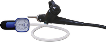
The umbilical cord contains the portion of the fiberscope that connects to the light source, including connectors for insufflation and irrigation in gastroscopes. Although the umbilical cord is not as fragile as the insertion tube, it still contains light-carrying fiber bundles and therefore should be handled with caution. Light sources for gastrointestinal fiberscopes may contain an integral air pump that provides air for insufflation. The same air pump provides the positive pressure that forces water from an attached bottle through the irrigation channel when the irrigation button on the handpiece is depressed. A separate connector for suction allows a tube to be attached to an independent suction pump. A pressure compensation valve in this region prevents damage from external pressure changes that may occur during ethylene oxide (ETO) gas sterilization or shipping by air when the pressure compensation cap is attached to the valve. A manometer-type pressure tester attached to this valve is used to check for internal leaks in the endoscope. When the pressure tester is attached (Figure 1-8), the bulb is repeatedly squeezed until the desired pressure is reached according to the manufacturer’s specifications. The needle of the pressure gauge should remain stable if the system is free of leaks. Pressure testing is quick and easy and should be done as a matter of routine before and after each procedure. Early detection of leaks may prevent costly water damage to the internal components of a fiberscope.
Fiberscope Optics
Because each fiber is only capable of transmitting a spot of uniform color and brightness, several thousand fibers must be arranged in a coherent order to transmit an image. Coherent bundles are formed by fusing the individual fiber faces of each end of the bundle in exactly the same pattern (Figure 1-9, A). The resolution and size of a fiberoptic image are determined in part by the number and size of individual fibers. Naturally, the possible size of an image bundle is limited in smaller diameter fiberscopes; consequently, the image size is reduced in these models. The optical benefits of reducing individual fiber diameter are also limited. With a reduction in fiber diameter, the ratio of cladding to core glass increases, resulting in reduced light transmission and a prominent honeycomb pattern that is more easily seen by the viewer.
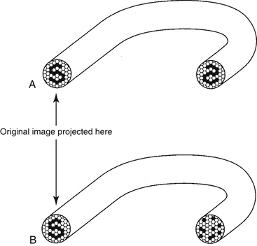
In addition to the image bundle (also called an image guide, IG), a fiberscope typically contains one or two light guide (LG) bundles that transmit light from the light source to the distal tip of the fiberscope to illuminate the area being examined. Although the fibers in the LG bundles may be similar to those in the IG bundles, they are not arranged in any particular pattern because they do not need to transmit an image. These fiber bundles are called incoherent bundles (see Figure 1-9, B).
Illumination lenses at each end of the LG bundles maximize the amount of light carried to the object being illuminated. The development of higher quality illumination lens systems and improvements in fiberoptic technology have been crucial in providing adequate brightness in the newer endoscopes with smaller diameters and greater fields of view.
Flexible Instruments
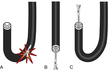
A variety of flexible instruments are available for use with endoscopes that have an accessory channel (see Figure 1-4). Both flexible and rigid endoscopes may accommodate the passage of flexible instruments, depending on their design. The most widely used instruments are for biopsy and foreign body retrieval. Biopsy instruments are described in detail in Chapter 8, and foreign body retrieval instruments are described in Chapter 7. Other popular flexible instruments include cytology brushes (Chapter 8), aspiration tubing, injection/aspiration needles, polypectomy snares, and coagulating electrodes. A vast number of styles and sizes are available; user preference and experience generally dictate which models work best.
Rigid and Semirigid Endoscopes
Flexible endoscopes are needed to thoroughly examine the depths of tubular structures that turn corners (e.g., intestine, bronchial tree, and male canine urethra), but rigid endoscopes are more convenient for examining nontubular structures, such as the abdominal cavity, thoracic cavity, or joint spaces. Rigid endoscopes, also known as telescopes, are also much simpler in design and less expensive than flexible endoscopes (Figure 1-10). Although they do contain glass lenses and fiberoptics, they do not contain the moving parts, flexible materials, and instrument channel of a flexible endoscope and can therefore easily last for many years with proper care.
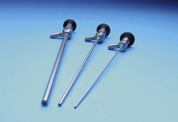
Figure 1-10 Rigid endoscopes (telescopes): 33-cm working length, 10-mm, 5-mm, and 3-mm diameter, respectively.
The original rigid endoscope was simply a hollow tube through which light was directed into a body cavity. The conventional telescope lens system (Figure 1-11, A) was first developed by Nitze in 1879. The next crucial breakthrough occurred in 1966, when Hopkins invented the rod lens system (Figure 1-11, B), which is still recognized as the gold standard of the industry. By employing complex optical physics algorithms, high-quality optical glass lenses, and robust manufacturing practices, a state-of-the-art rod lens system offers several significant improvements in image quality, including better light transmission, higher resolution and contrast, greater magnification, and a wider field of view. The wide variety of available rigid endoscopes and the visual access provided by even the smallest models open up an enormous field of minimally invasive diagnostic and therapeutic possibilities to veterinary practitioners. Indeed, the use of this technology in veterinary practice has expanded considerably since the mid-1990s.
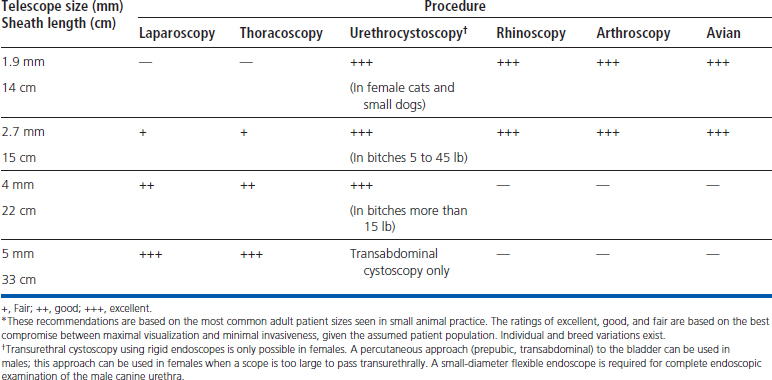
Rigid and semirigid endoscopes have outer diameters ranging from about 1 to 10 mm. Larger scopes have greater light-carrying capacity and produce larger images. Smaller scopes are less invasive and fit into smaller areas (e.g., nasal passages, female urethras, and joints). Some of the more common applications of rigid endoscopy in small animal medicine include laparoscopy, thoracoscopy, urethrocystoscopy, rhinoscopy, laryngoscopy, arthroscopy, vaginoscopy, otoscopy, and avian and exotics endoscopy. As with flexible endoscopes, no one size of rigid or semirigid endoscope is suitable for all procedures in all patients. The appropriate-sized telescope should be selected on the basis of the procedures most commonly performed (Table 1-2). Although smaller telescopes tend to be more versatile, they are also more prone to breakage and illumination is limited when these scopes are used in larger, more light-absorptive cavities (e.g., thorax and abdomen).
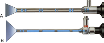
The viewing angle of a telescope is an important consideration because it affects both orientation and visual access (Figure 1-12). Forward-viewing telescopes (0 degrees) provide the simplest orientation but a relatively limited viewing field, centered on the axis of the telescope. A 25- or 30-degree viewing angle allows the endoscopist to view a larger area by simply rotating the telescope on its longitudinal axis. Spatial orientation becomes more challenging with an oblique-viewing scope, but as more experience is gained, the operator can become quite proficient in its use. Some telescopes are available in even more acute angles of view (e.g., 70, 90, and 120 degrees), but these instruments are rarely used in veterinary practice. The choice of telescope largely depends on the procedure being performed and the experience of the endoscopist.
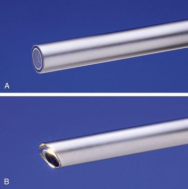
Figure 1-12 Telescope viewing angles. A, 0 degrees. B, 30 degrees.
(Photos courtesy of Karl Storz GmbH & Co. KG, Tuttlingen, Germany.)
Rigid endoscopes are typically used in conjunction with some type of sheath or cannula, which serves several purposes: it provides access to the anatomic site, protects the telescope and patient, and facilitates the ingress or egress of fluids or gas, as well as the introduction of diagnostic or surgical instruments. By convention, a sheath is usually locked onto the telescope, as in the case of an arthroscope sheath (Figure 1-13) or cystoscope sheath. A cannula, on the other hand, usually refers to a tube through which the telescope or instrument passes freely (without locking), as in the case of a laparoscope cannula (Figure 1-14) or arthroscope instrument cannula.
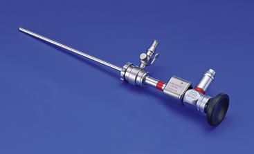
Figure 1-13 The 2.7-mm Multi-Purpose Rigid endoscope locked in place in an arthroscope sheath.
(Photo courtesy of Karl Storz GmbH & Co. KG, Tuttlingen, Germany.)
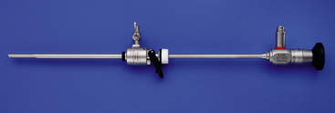
Figure 1-14 A 5-mm laparoscope with cannula used for laparoscopy and thoracoscopy.
(Photo courtesy of Karl Storz GmbH & Co. KG, Tuttlingen, Germany.)
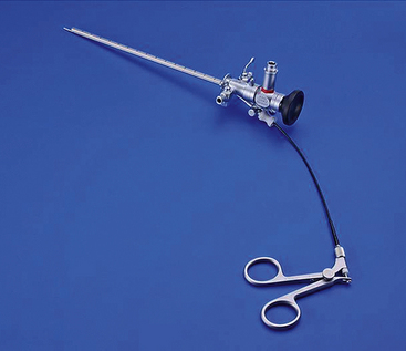
The most popular telescope used today in small animal practice is the 2.7-mm Multi-Purpose Rigid endoscope. Frequently referred to as an arthroscope, this versatile telescope is ideally suited for many other procedures including urethrocystoscopy in females, rhinoscopy, otoscopy, and avian celioscopy. The popular “operating sheath” for this telescope, originally designed for human pediatric cystoscopy, accommodates 5F flexible instruments and allows the introduction of fluids or gas (Figure 1-15). A variety of sheaths and cannulae are available for the Multi-Purpose Rigid endoscope (Figure 1-16), each designed to suit the anatomy and functional requirements of different procedures.
Stay updated, free articles. Join our Telegram channel

Full access? Get Clinical Tree


