Chapter 11 Stapling and Energy Devices for Endoscopic Surgery
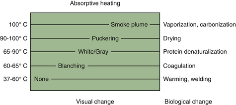
The past 10 years have seen significant advances in surgical devices geared toward operative dissection and hemostasis. Advanced electrosurgical generators, ultrasonic scalpels, and surgical lasers are examples of such. Although they exert their effects via different physical principles, they are best viewed simply as different means of delivering energy to tissue. Tissue effects are ultimately mediated by thermal changes, which are predictable despite the operative method (Figure 11-1). No one particular system is inherently superior to the other. Each has its advantages and disadvantages for a given procedure. Unfortunately, the choice of an energy modality is frequently more a function of surgeon familiarity and training rather than an informed decision.
Endosurgical Clips and Staplers
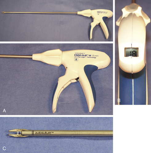
Endosurgical clip appliers were developed in 1990 and were used extensively in humans to perform laparoscopic cholecystectomy, one of the first major laparoscopic treatments in people. Surgical clip appliers have a place in every endoscopist’s armamentarium. A single clip application may negate the need to convert to an open procedure. Modern clip appliers can be precocked before placement, which allows the clip to be advanced proximal or distal along a tubular structure before closure. The distal tips of the clip are closed first, which prevents tissue from being squeezed laterally beyond the clip margins before closure. Some form of clip counter is visible on the instrument and ensures sufficient clip numbers to complete the procedure (Figure 11-2).
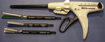
Multifire endostapler cartridges (DLUs) come in a variety of lengths and configurations (Figure 11-3). The staples themselves are composed of titanium and are formed into a B shape as they are applied against the cartridge anvil during the firing cycle. The B shape allows microvascular perfusion to the staple line, which prevents necrosis that could lead to delayed hemorrhage or leakage. Available options include an integrated cutting blade as well as a roticulating hinge. Roticulation is defined as the ability to simultaneously rotate and articulate and requires the appropriate endostapler as well as stapler cartridge. Note that the use of a roticulating as opposed to a simple straight cartridge adds approximately 1.5 cm of length to the DLU, which can be an important consideration when working in a tight space, such as the chest.
Electrosurgical Generators
The first electrosurgical generator was developed by Harvey Cushing and William Bovie in the 1920s. Early electrosurgical generators that followed from their original “Bovie” were deficient primarily in two areas: patient safety and consistent tissue effect. Advances in computer and electronics technologies in the past 20 years have not only addressed these issues but also established electrosurgery as the preferred standard in many operating theaters.
Theory
where V = voltage; I = current; and R = resistance to flow
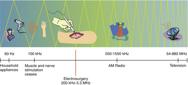
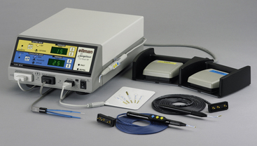
Household electricity is supplied as 110-volt, alternating current at 60 Hz. That is, the current is supplied as a sine wave, which changes polarity from positive to negative at 60 cycles per second. The neuromuscular system becomes refractory to electrical stimulation beyond a frequency of 100,000 Hz. For this reason, modern electrosurgical generators utilize frequencies in the range of 350,000 to 500,000 Hz, which falls within the medium radiofrequency electromagnetic spectrum (Figure 11-4). Some units may go as high as 3 to 4 megahertz (MHz) and deserve special mention (Figure 11-5). These units are commonly referred to as radiosurgery units, but this terminology is not only confusing but incorrect. By medical convention, the term radiosurgery applies to the use of a targeted beam of ionizing radiation used primarily for cancer ablation. The correct terminology for high-frequency electrosurgical application as referenced here is radio wave radiosurgery (RWRS). This type of system will be discussed separately in a subsequent section.
When direct current is allowed to flow through a wire connecting the positive and negative poles of an electrical circuit, the wire itself becomes hot. When this heated wire loop is brought into contact with tissue, the heat of the wire exerts a tissue effect proportional to its magnitude. This is referred to as electrocautery. This is in contrast with the system that is utilized in modern electrosurgical generators, whereby alternating current from an active electrode is allowed to pass through the patient’s body to a passive or dispersive electrode, and then back to the generator box. Although seemingly a minor point, it is important to realize this distinction, as the literature is fraught with references to electrocautery when electrosurgery as applied by an electrosurgical unit (ESU) is what is actually meant.
Power is defined by the following relationship:
where P = power; V = voltage; and I = current
Waveforms
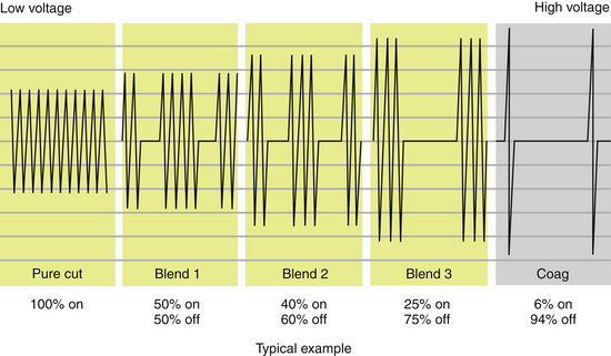
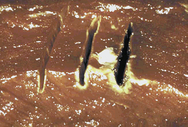
Electrosurgical waveforms consist of essentially three types: cutting, coagulating, and blended (Figure 11-6). The cutting and blended waveforms are continuous and use less peak voltage than a coagulating waveform at the same power setting. Higher peak voltages result in greater lateral thermal damage to the target tissue. This is clinically apparent when tissue is incised with three different waveforms applied at the same power setting (Figure 11-7). For this reason, it is important for the surgeon to have a fundamental understanding of the physics of electrosurgery rather than relying exclusively on the selected waveform to exert its designated effect. Another clinically relevant example lies in the application of energy to a hemostat to achieve coagulation of a vessel. Intuitively, one would expect the operator to apply coagulating energy to the hemostat, when in fact this is not recommended practice. Cutting energy should be applied to the hemostat, as lesser voltage is utilized with less thermal spread. In fact, cutting energy can be used to effect hemostasis and is often underutilized in this capacity. Cutting energy is capable of producing deeper hemostasis than that achieved with coagulating energy. The reason for this lies in the fact that coagulating energy produces greater thermal damage, resulting in rapid buildup of tissue resistance from char accumulation at the tissue–electrode interface. As tissue resistance increases, greater power is needed to penetrate deeper tissue. With cutting energy, tissue heats up more quickly, steam forms as cells explode, and there is less char accumulation. Energy is able to penetrate deeper into the target tissue without stalling at the point of tissue damage.
Many surgeons prefer to use blended energy for nearly all tissue applications, considering it to be a tradeoff between tissue damage and inadequate hemostasis. As noted in Figure 11-6, blended energy is delivered as an interrupted waveform, with varying degrees of on and off time. As the percent of on time is increased, the more rapidly tissue is desiccated and hemostasis is achieved.
Monopolar Systems
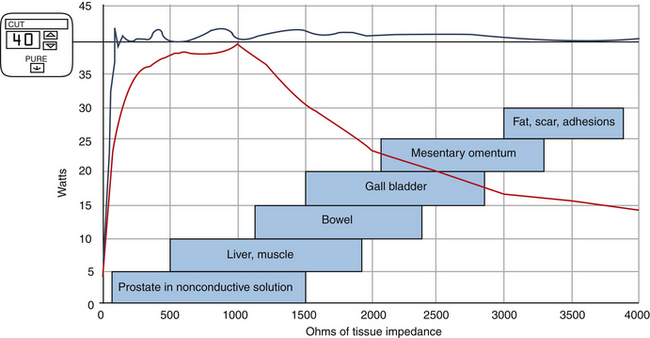
The generator box (ESU) converts standard 60-Hz, 110-volt current into an operator-selected waveform and power delivered at 300 to 500 KHz. The first monopolar generators were totally dependent on the operator with respect to ultimate tissue effect. Variations in time of application as well as inconsistent power delivery made for inconsistent results. With the advent of computer-modulated circuitry, however, huge advances were made to allow nearly real-time monitoring of tissue impedance. Modern generators sense tissue impedance at 200 times per second and alter voltage and current to deliver consistent power over a wide range of tissue impedances. The end result is much more consistent tissue effects (Figure 11-8).
Stay updated, free articles. Join our Telegram channel

Full access? Get Clinical Tree


