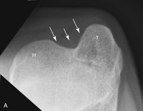
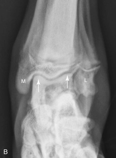
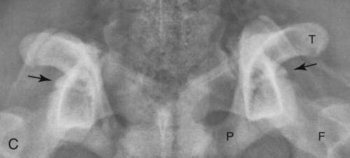
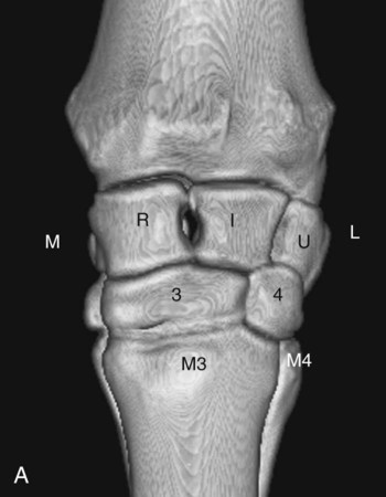
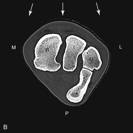
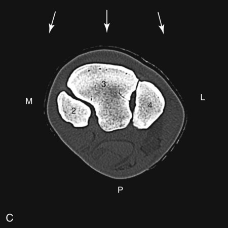
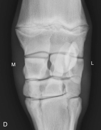
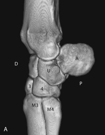
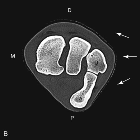
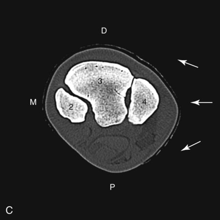
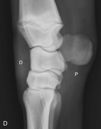
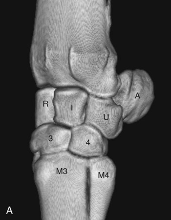
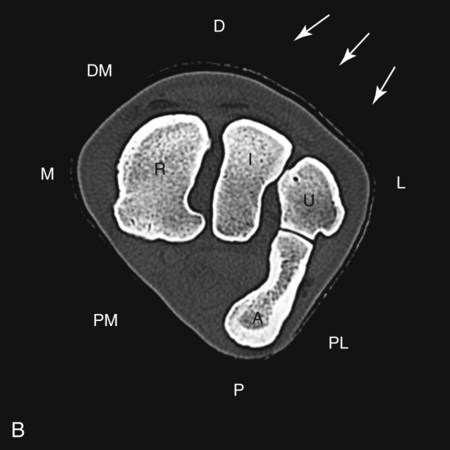
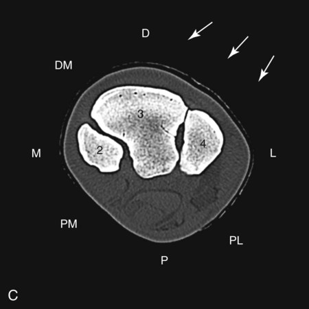
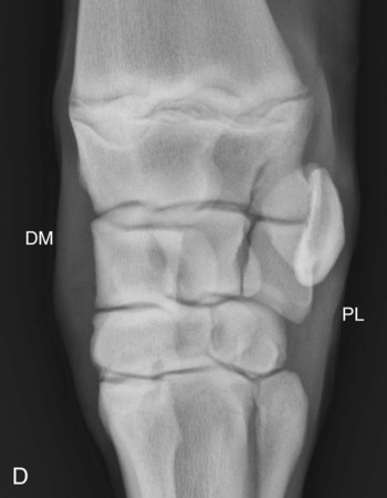
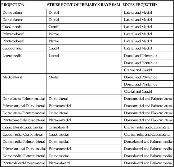
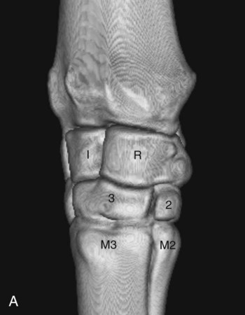
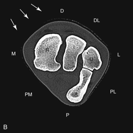
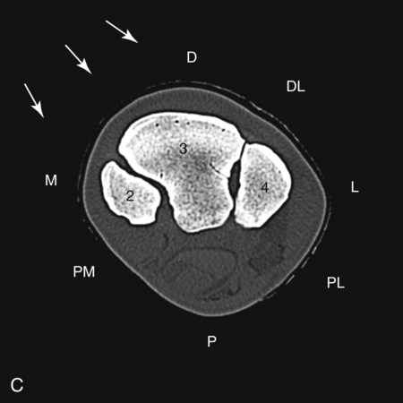
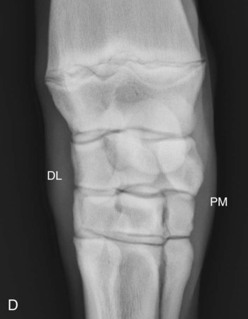
Following the general principles of radiographic geometry that were discussed in Chapter 5, radiographic examination of structures in the appendicular skeleton in dogs and cats should consist of a minimum of two orthogonal projections, a lateral view and a craniocaudal (dorsopalmar, dorsoplantar) view. If a bone lesion is suspected, it is important that the field of view include the joint proximal and distal to the bone of interest. If a joint is being investigated, the primary x-ray beam should be centered on the joint. Also discussed in Chapter 5, the terminology used for radiographs of an extremity made with the x-ray beam striking the front or back of a limb depends on whether it is a front limb or hind limb and whether the center of the x-ray beam strikes the limb proximal or distal to the antebrachiocarpal or tarsocrural joint. In spite of being named differently, whether the x-ray beam strikes the front or back of a limb for any given projection, dorsoplantar versus plantarodorsal for example, does not affect the appearance of the radiograph in most instances because the radiograph is a two-dimensional representation of a three-dimensional object. 1. Cranioproximal-craniodistal view of canine proximal humerus for evaluation of bicipital groove for changes associated with biceps or supraspinatus tendinopathy (Fig. 14-1, A) 2. Flexed dorsoplantar view of canine tarsus for evaluation of trochlea of talus for changes associated with osteochondrosis, without superimposition of calcaneus (Fig. 14-1, B) 3. Dorsal acetabular rim view of canine pelvis for evaluation of lateral aspect of acetabulum for remodeling (Fig. 14-1, C) The views in Figure 14-1 do not encompass all ancillary views that have value in appendicular radiography and are provided only as examples of how changing the orientation of the x-ray beam and skeleton can lead to projection of clinically important surfaces that cannot be assessed adequately in the standard projections. These ancillary views, and others, are discussed throughout the textbook where appropriate, and examples of representative abnormalities are provided. One aspect of equine radiography that deserves special mention is the common practice of holding the cassette by hand. Equine-extremity radiographs are almost always acquired with the horse in a standing position, and handholding the cassette is convenient. However, handholding of cassettes increases the chance that occupational radiation exposure limits will be exceeded or radiation safety practices will be compromised. Individuals handholding a cassette for equine radiography should wear protective lead aprons and lead gloves, as well as a thyroid shield and protective lead glasses. It must be remembered that this equipment protects only against scattered photons, and the gloved hand must never be placed in the primary x-ray beam; this was addressed in detail in Chapter 1. Also noted in Chapter 1, rotation of technical personnel in and out of the equine radiology service will distribute the occupational radiation dose over a larger number of people and minimize individual exposure doses. It is important to understand the geometry of oblique projections so that the location of abnormalities can be understood. The concept of oblique projections will be illustrated using the equine carpus as an example, but the principles apply to other regions and other joints. The principles of oblique projections based on radiography of a canine carpus are also available.1 Labeled oblique radiographs of equine and canine joints are included in Chapter 13. The edges projected in an oblique radiograph of a limb can be deduced by understanding the geometry of these projections, which is reviewed in Table 14-1 (page 258) and in Figures 14-2 through 14-5 (pages 254-257). In Figures 14-2 through 14-5, the imaging plate or cassette is oriented perpendicular to the primary x-ray beam, but the imaging plate is not shown for the sake of clarity. Table • 14-1 Summary of Edges Projected in Oblique Radiographs
Principles of Radiographic Interpretation of the Appendicular Skeleton
Positioning: Dog and Cat
Positioning: Horse
Oblique Projections
PROJECTION
STRIKE POINT OF PRIMARY X-RAY BEAM
EDGES PROJECTED
Dorsopalmar
Dorsal
Lateral and Medial
Dorsoplantar
Dorsal
Lateral and Medial
Craniocaudal
Cranial
Lateral and Medial
Palmarodorsal
Palmar
Lateral and Medial
Plantarodorsal
Plantar
Lateral and Medial
Caudocranial
Caudal
Lateral and Medial
Lateromedial
Lateral
Dorsal and Palmar, or
Dorsal and Plantar, or
Cranial and Caudal
Mediolateral
Medial
Dorsal and Palmar, or
Dorsal and Plantar, or
Cranial and Caudal
Dorsolateral-Palmaromedial
Dorsolateral
Dorsomedial and Palmarolateral
Palmaromedial-Dorsolateral
Palmaromedial
Dorsomedial and Palmarolateral
Dorsolateral-Plantaromedial
Dorsolateral
Dorsomedial and Plantarolateral
Plantaromedial-Dorsolateral
Plantaromedial
Dorsomedial and Plantarolateral
Craniolateral-Caudomedial
Craniolateral
Craniomedial and Caudolateral
Caudomedial-Craniolateral
Caudomedial
Craniomedial and Caudolateral
Dorsomedial-Palmarolateral
Dorsomedial
Dorsolateral and Palmaromedial
Palmaromedial-Dorsomedial
Palmaromedial
Dorsolateral and Palmaromedial
Dorsomedial-Plantarolateral
Dorsomedial
Dorsolateral and Palmaromedial
Plantarolateral-Dorsomedial
Plantarolateral
Dorsolateral and Palmaromedial

Stay updated, free articles. Join our Telegram channel

Full access? Get Clinical Tree


Principles of Radiographic Interpretation of the Appendicular Skeleton

