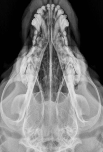
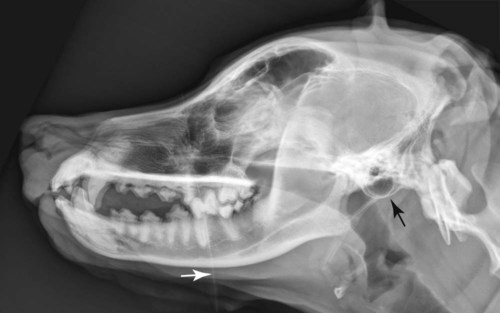
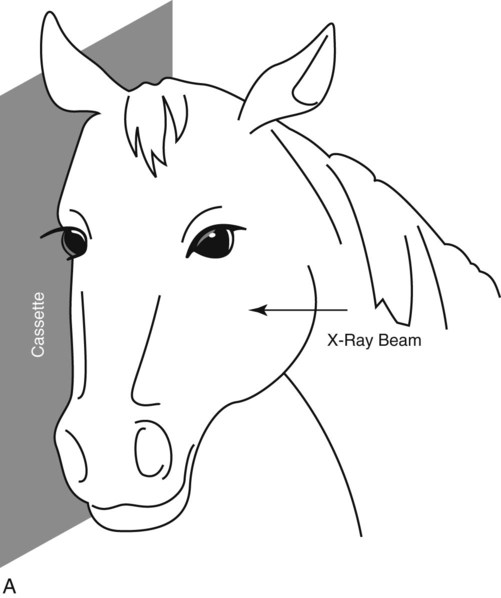
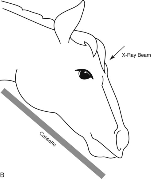
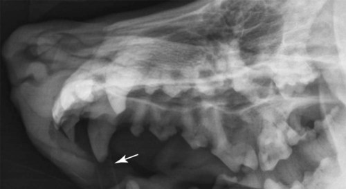
Lateral and dorsoventral (DV) views are the minimum radiographic projections of the canine and feline skull to acquire. The DV view is preferred over the ventrodorsal (VD) view, because for the DV view the mandibles can be compressed mildly against the x-ray table, which facilitates obtaining a symmetrically positioned radiograph (Fig. 7-1). This assumes that there is not mandibular asymmetry, as from a fracture or a mass for example, which would make it impossible to position the head symmetrically using the mandibles as a guide. As the dorsal surface of the head is rarely flat, extreme care must be taken to position the head symmetrically if a VD view is attempted. For the lateral view, the dog or cat cannot be allowed to rest naturally on the x-ray table. Radiolucent sponges will be needed to elevate the nose in most patients. Sponges may also be needed to elevate the mandibles. The goal is to have left-sided and right-sided structures superimposed perfectly in the resultant radiograph (Fig. 7-2). Care must be taken to keep the positioning devices free of dirt and debris that can introduce artifacts into the image (see Fig. 7-2). The mouth can be either left closed or held open with a speculum. If the disease affects the mandible or maxilla, then there is value in having the mouth open to reduce superimposition. Because of the complexity of the skull, many ancillary projections have been devised to increase the conspicuity of certain regions. These are listed in Table 7-1, and a few selected examples are included here (Figs. 7-3 through 7-9). Space does not permit a thorough discussion of each of the ancillary views that are available for use in the skull, but other sources are available.1,2 These ancillary views are not used routinely but are selected based on the purpose of the radiographic examination. Many ancillary views of the skull involve having the skull at an angle with respect to the primary x-ray beam; this requires changing the position of the patient. Some other ancillary views actually require that the x-ray beam be angled from its normal perpendicular perspective with respect to the x-ray table; this requires having an x-ray machine with an x-ray tube head that can be (1) moved longitudinally along the top of the x-ray table and (2) rotated clockwise or counterclockwise to angle the primary x-ray beam. Table • 7-1 Ancillary Radiographic Projections of the Canine or Feline Skull *Any angle specified in this table for this or any other ancillary skull radiograph is an estimate. This will vary among dogs and should be selected based on visual determination of the angle that results in optimal isolation of the area of interest. An important aspect regarding oblique radiographs of the skull is making sure that a reliable external marking system has been used so that left can be distinguished from right in the image. It is helpful to use both “L” and “R” markers on the same image to designate which structures are being projected (Fig. 7-10). Taking the time to define a suitable marking system for your practice and explaining it thoroughly to personnel will save confusion in the long run. This is a situation where identification of a radiology supervisor, discussed in Chapter 1, is valuable because he or she can become familiar with the marking system and ensure that it is used correctly and routinely. For the lateral view, the cassette is positioned against the side of the head and the x-ray beam directed from the opposite side (Fig. 7-11, A). The position of the cassette and x-ray beam can be adjusted for acquiring radiographs of different regions of the skull, such as the nasal cavity versus the brain case versus the guttural pouches. Another thing to keep in mind for the lateral view is the effect of magnification. Because of the thickness of the equine skull, a lesion on the x-ray tube side of the skull will be magnified considerably and may not be conspicuous because of blurring. Thus if the location of the lesion is known, the cassette should be held against that side of the head and the x-ray beam directed from the opposite side. If the location of the lesion is not known, it is good practice to obtain both the left-right and right-left radiographs of the skull to make sure that a lesion is not overlooked because of magnification. For the DV view, the cassette is held ventral to the mandibles and the x-ray beam directed onto the dorsal aspect of the head (Fig. 7-11, B). It is important to keep the x-ray beam perpendicular to the cassette. As noted before, sedation is very helpful for obtaining the DV view because as the horse lowers its head in response to the sedative, the positioning of the x-ray tube dorsally is facilitated. Without sedation one might be able to acquire a DV view of the nasal passage, but a DV view of the calvaria or brain case will not be possible. VD views of the skull are not made in the standing horse.
Principles of Radiographic Interpretation of the Axial Skeleton
Skull
Positioning: Dog and Cat
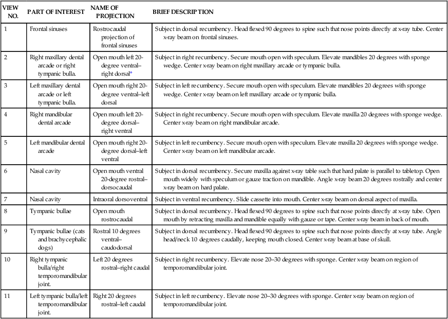
VIEW NO.
PART OF INTEREST
NAME OF PROJECTION
BRIEF DESCRIPTION
1
Frontal sinuses
Rostrocaudal projection of frontal sinuses
Subject in dorsal recumbency. Head flexed 90 degrees to spine such that nose points directly at x-ray tube. Center x-ray beam on frontal sinuses.
2
Right maxillary dental arcade or right tympanic bulla.
Open mouth left 20-degree ventral–right dorsal*
Subject in right recumbency. Secure mouth open with speculum. Elevate mandibles 20 degrees with sponge wedge. Center x-ray beam on right maxillary arcade or tympanic bulla.
3
Left maxillary dental arcade or left tympanic bulla.
Open mouth right 20-degree ventral–left dorsal
Subject in left recumbency. Secure mouth open with speculum. Elevate mandibles 20 degrees with sponge wedge. Center x-ray beam on left maxillary arcade or tympanic bulla.
4
Right mandibular dental arcade
Open mouth left 20-degree dorsal–right ventral
Subject in right recumbency. Secure mouth open with speculum. Elevate maxilla 20 degrees with sponge wedge. Center x-ray beam on right mandibular arcade.
5
Left mandibular dental arcade
Open mouth right 20-degree dorsal–left ventral
Subject in left recumbency. Secure mouth open with speculum. Elevate maxilla 20 degrees with sponge wedge. Center x-ray beam on left mandibular arcade.
6
Nasal cavity
Open mouth ventral 20-degree rostral–dorsocaudal
Subject in dorsal recumbency. Secure maxilla against x-ray table such that hard palate is parallel to tabletop. Open mouth widely with speculum or gauze traction on mandible. Angle x-ray beam 20 degrees rostrally and center x-ray beam on hard palate.
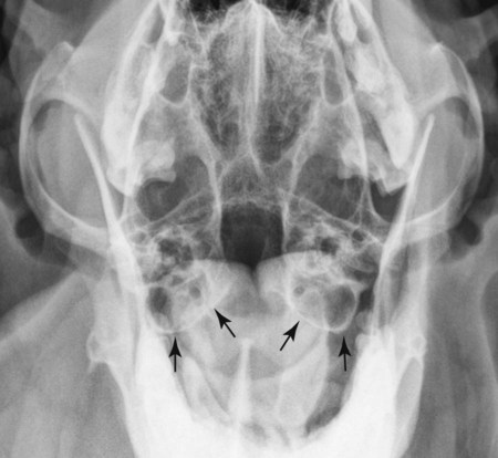
7
Nasal cavity
Intraoral dorsoventral
Subject in ventral recumbency. Slide cassette into mouth. Center x-ray beam on dorsal aspect of maxilla.
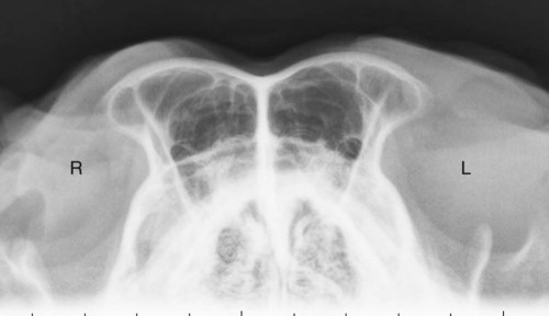
8
Tympanic bullae
Open mouth rostrocaudal
Subject in dorsal recumbency. Head flexed 90 degrees to spine such that nose points directly at x-ray tube. Open mouth by retracting maxilla and mandible equally with gauze or tape. Center x-ray beam in back of mouth.
9
Tympanic bullae (cats and brachycephalic dogs)
Rostral 10 degrees ventral–caudodorsal
Subject in dorsal recumbency. Head flexed 90 degrees to spine such that nose points directly at x-ray tube. Angle head/neck 10 degrees caudally, keeping mouth closed. Center x-ray beam at base of skull.
10
Right tympanic bulla/right temporomandibular joint.
Left 20 degrees rostral–right caudal
Subject in right recumbency. Elevate nose 20–30 degrees with sponge. Center x-ray beam on region of temporomandibular joint.
11
Left tympanic bulla/left temporomandibular joint.
Right 20 degrees rostral–left caudal
Subject in left recumbency. Elevate nose 20–30 degrees with sponge. Center x-ray beam on region of temporomandibular joint.
Positioning: Horse
![]()
Stay updated, free articles. Join our Telegram channel

Full access? Get Clinical Tree


Principles of Radiographic Interpretation of the Axial Skeleton