chapter 19 Large Animal Radiography
INTRODUCTION
Working with large animal patients requires much patience and time. Any procedure performed must be well thought out before it is started. The radiographer must also expect the unexpected. Successful large animal radiography is the result of forming a plan before the examination, teamwork during the examination, and patience throughout.
SPECIAL CONSIDERATIONS
Equipment
The portable unit is commonly used by equine and bovine veterinary practitioners who make “house calls.” The portable unit is small and light enough that it can easily be moved from one location to another (seeFig. 2-4). The average power capacity of a portable unit is limited to a maximum milliamperage (mA) setting of 20 and a maximum kilovoltage (kVp) of 90. Due to the low mA capability, exposure times of 0.1 second or longer usually are necessary. However, long exposure times increase the likelihood of motion during exposure. Because line voltage varies from barn to barn, exposures are not always consistent with portable units. The collimation on a portable unit also varies, and the collimator may not always have a light to visualize the field of exposure. Therefore it is often easy to expose an area larger than necessary. This can pose a special problem with radiation safety (i.e., the exposure of personnel to excessive radiation).
Mobile units have the advantage of more power. The capacity of an average mobile unit ranges from 100 to 300 mA and up to 120kVp. The higher mA capacity allows for shorter exposure times. The main disadvantage of this unit is its weight and consequent lack of maneuverability. The mobile unit has large wheels to allow ambulation but tends to be cumbersome and difficult to move on uneven floor surfaces (seeFig. 4-2).
Large, permanently mounted x-ray units are commonly used by veterinary specialty and referral practices. The power capacity may exceed 1000 mA. For large animal radiography, these units are commonly mounted on the ceiling with a series of overhead rails, which allow the x-ray tube to be moved vertically and horizontally around the patient (seeFig. 2-19, B). Unfortunately, ceiling units that have overhead rails can be noisy and distracting to a fearful patient. In addition, the size of the x-ray tube housing may limit its use for studies of the feet. Even if the tube is on the floor, the focal spot may be 6 to 8 inches off the floor, resulting in obliquity of the views.
Patient Preparation
Careful preparation of the patient is necessary for an artifact-free radiograph. For all examinations, the hair coat should be brushed or washed to remove obvious dirt, bedding, and other surface artifacts. The areas of interest also should be wiped dry with a towel to remove any water or other remaining liquid contaminants. For radiography of the equine foot, a number of steps are necessary to prevent extraneous radiographic shadows over the areas under examination. The first step is to remove the shoe of the patient and trim back any overgrown portions of the hoof. Next, the sole and clefts should be picked and scrubbed clean. The final step is to pack the sole of the foot with a radiolucent material such as methylcellulose, softened soap, or Play-Doh. Packing the sole prevents the appearance of an air artifact superimposed over the areas of interest.
Radiation Safety
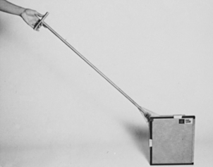
The attendants holding the patient and holding the cassette next to the anatomy must be wearing appropriate lead attire. Because the attendants’ attention is focused on the patient rather than the x-ray beam, it is the responsibility of the radiographer to ensure that all personnel are a safe distance from the primary beam. Cassette-holding devices help reduce exposure to the attendants. The device usually consists of a clamp that is attached to the cassette and held at length by a handle (Fig. 19-1).
Positioning Devices
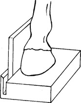
At times, it may be necessary to raise the animal’s foot because the x-ray tube cannot be dropped to the level of the floor. A positioning block can be used to raise the foot into position and to serve as a cassette holder (Fig. 19-2). The block is usually constructed of wood built to suit the particular x-ray unit. A slot can be cut into the wood to serve as a cassette holder. The foot of the patient can be placed directly onto the block to raise it into position next to the cassette, or the cassette can be placed beside the block.
Another device that is often necessary is a cassette tunnel. A tunnel can be constructed of a radiolucent wood or hard plastic, but it must be durable enough to withstand the weight of the patient. For a dorsopalmar/dorsoplantar oblique view of the coffin or navicular bone, the patient must be standing on top of the cassette. A cassette cannot withstand such weight without sustaining damage. A tunnel device can make the examination possible without damaging the equipment (Fig. 19-3).
Lateral View
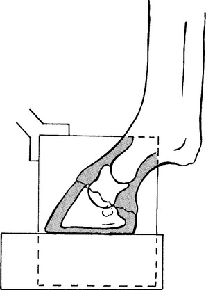
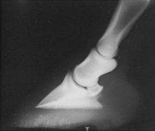
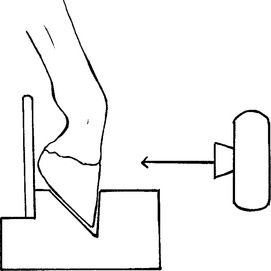
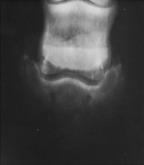
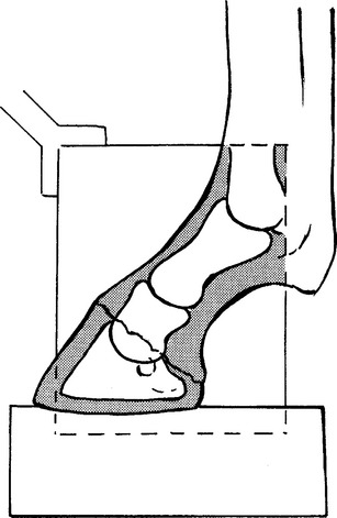
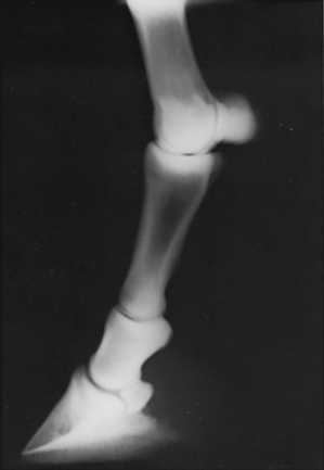
The patient’s foot is placed on a wood block to elevate it to a level at which the central x-ray beam can be directed horizontally toward the pedal bone. The placement of the foot must be as close to the edge of the block as possible so that the cassette is as close to the medial aspect of the foot as possible (Figs. 19-4 and 19-5). The object–film distance must be minimal. To prevent motion, it may be helpful to have an attendant hold the patient’s leg of interest over the carpus or elevate the opposite limb so that the limb being examined is completely weight bearing. The cassette is placed on the medial side of the foot, either directly on the floor or in the cassette groove in the wood block. The field of view should include the entire hoof. (NOTE: This same position is used to examine the lateral navicular bone. In that case, the beam center is directed at the palmar aspect of the coronary band.)
Dorsopalmar/Dorsoplantar View
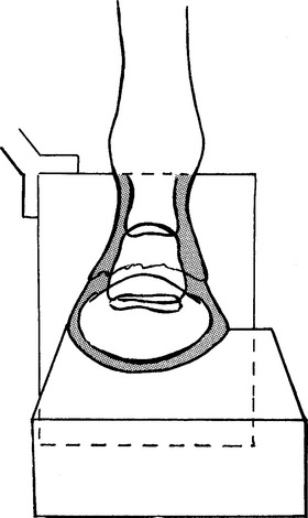
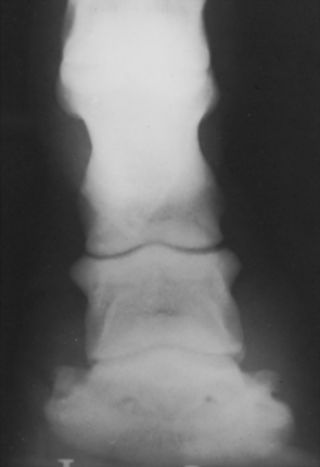
The patient’s foot is placed on a wood block so that it is elevated to the level of the horizontal central x-ray beam. The heel of the foot should be placed on the edge of the block or cassette groove. The cassette is placed directly behind the foot on the floor or in the cassette groove and held perpendicular to the floor (Figs. 19-6 and 19-7). It may be helpful to raise the opposite limb so that full weight is placed on the limb of interest. This decreases the possibility of motion. The field of view should include the entire hoof.
BEAM CENTER: Over middle of pedal bone just below coronary band
Dorsopalmar/Dorsoplantar Oblique View
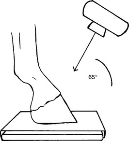
The cassette is placed in a tunnel cassette holder, and the foot of the patient is positioned on top of the tunnel. The foot should be in the center of the cassette so that the entire hoof and pedal bone are included in the field of view (Figs. 19-8 and 19-9). It may be necessary to raise the opposite limb so that the limb of interest is weight bearing. The x-ray tube is angled 45 degrees to the ground and directed at the hoof wall. (NOTE: This same view can be used to visualize the navicular bone. Because of superimposition of the navicular bone over the second phalanx, higher exposure factors are necessary to visualize this area, and an angle of 65 degrees off horizontal should be used.)
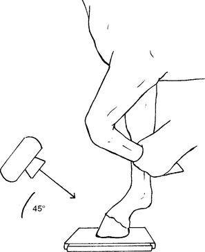
Figure 19-8 Correct positioning for the dorsopalmar/dorsoplantar oblique view of the distal phalanx.
BEAM CENTER: Over middle point of hoof wall just below coronary band
Dorsopalmar/Dorsoplantar Oblique View
The patient’s foot can be placed (1) on a cassette within a cassette tunnel, as shown for the dorsopalmar/dorsoplantar oblique view of the distal phalanx, or (2) on a block with specially designed grooves that hold the hoof at an angle (Figs. 19-10 through 19-12). With the patient standing on the cassette, the x-ray beam is angled 65 degrees toward the middle of the second phalanx. When the block is used, the toe of the hoof is placed in a vertical groove so that the dorsal wall of the hoof is positioned vertically. The cassette is placed behind the heels in a cassette groove. The opposite leg must bear the majority of the patient’s weight. The x-ray beam is directed parallel to the ground, and the field of view should include the second and third phalanges. With the foot on the block in this vertical position, a 45- to 65-degree angle view of the navicular bone is projected onto the x-ray film.
BEAM CENTER: Over center of second phalanx just above coronary band
Flexor View
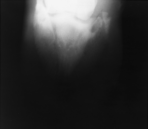
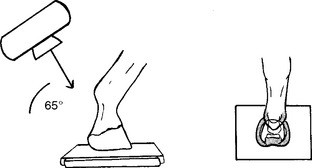
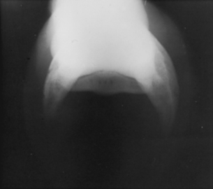
The foot of the patient is placed on top of a cassette within a cassette tunnel (Figs. 19-13 and 19-14). If possible, the patient should be stepping back slightly so that the fetlock is in an extended position. The first phalanx is almost perpendicular to the ground in this position, allowing better visualization of the navicular bone. The x-ray tube is positioned directly behind the foot and angled approximately 65 degrees to the floor. Great care must be taken with the x-ray tube in this position immediately behind the limb. It may be necessary to reduce the source–image distance (SID) when placing the x-ray tube under the belly of a horse for views of the front navicular bone.
Lateral View (Short and Long Pastern)
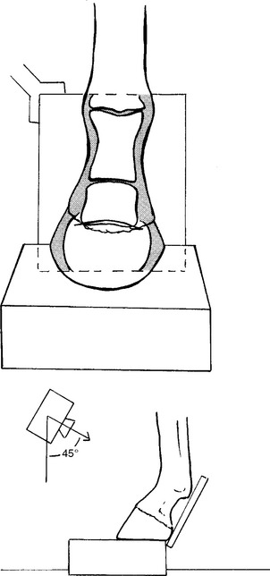
The foot of the patient is placed on a wood block so that it is elevated slightly off the floor. The cassette is placed next to the medial aspect of the foot and should be on and perpendicular to the floor. The limb of interest should be weight bearing (Figs. 19-15 and 19-16). It may be necessary to raise the opposite limb to eliminate motion. The x-ray beam is directed horizontally toward the phalanx. The field of view should include the first and second phalanges for a general projection of the area.
Dorsopalmar/Dorsoplantar View
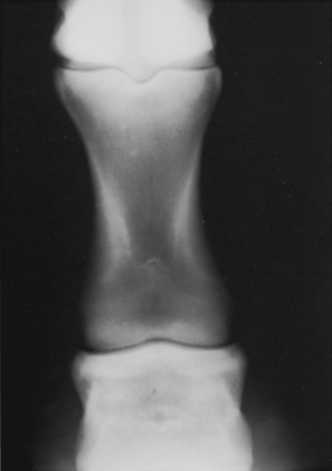
The patient is positioned so that the limb under examination is weight bearing. The cassette is placed behind the limb parallel to the phalanges (Figs. 19-17 and 19-18). It may be necessary to elevate the opposite limb to minimize motion. Depending on the angle of the foot and the placement of the cassette, it may be necessary to direct the x-ray tube at a 30- to 45-degree angle to the floor. The x-ray beam must be perpendicular to the cassette. The field of view should include the first and second phalanges.
Dorsopalmar/Dorsoplantar View
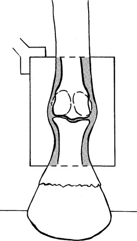
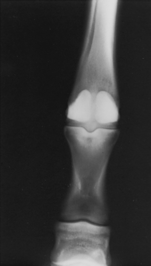
The foot of the patient is placed with full weight on the floor directly under the body. The cassette is positioned on the floor directly behind the foot, touching the palmar or plantar aspect of the digit. The cassette should be held perpendicular to the floor (Figs. 19-19 and 19-20). The opposite limb may be elevated if necessary to control the patient. The field of view should include the entire fetlock joint and a small portion of the bones that are proximal and distal to the joint. (NOTE: Aiming the x-ray beam at a slight tilt downward minimizes the sesamoid superimposition on the joint surfaces.)
Lateral View
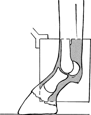
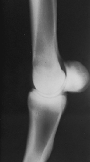
The foot of the patient is placed in a weight-bearing position directly under the body. The cassette is placed on the floor on the medial side of the foot of interest. The cassette should remain perpendicular to the floor (Figs. 19-21 and 19-22). Raising the opposite limb may be necessary to control the patient. The field of view should include the fetlock joint and a small portion of the bones proximal and distal to the joint.
Stay updated, free articles. Join our Telegram channel

Full access? Get Clinical Tree


