Chapter 15 Radiography and Radiology
Radiography is the acquisition of radiographic images; radiology is the study and interpretation of those images. Radiography is an important part of the diagnostic armamentarium in the evaluation of lameness. Its most important role is to give information about bones and joints. However, it also can provide information about soft tissues, most particularly tendon, ligament, and joint capsule insertions. If radiography is to be used properly, then the area under investigation must be evaluated comprehensively and appropriately. A sufficient number of views, all which have been appropriately centered and exposed, should be obtained.
Obtaining high-quality radiographic images requires attention to detail. The horse must be correctly positioned and adequately restrained or sedated. For most weight-bearing examinations the horse should stand with the cannon bone of the limb to be examined in a vertical position. The horse should be standing on all four limbs, not resting a limb. The area under investigation should be cleaned to remove any surface dirt. For examinations of the foot, the shoe should be removed (if possible) to facilitate proper paring of the sole and frog, to ensure it is adequately clean, and to avoid superimposition of a radiodense shoe over the distal phalanx and navicular bone. The tail should be tied to facilitate correct positioning of the cassette or imaging plate when the stifle and hock regions are examined.
Radiographic Detail
The aim is to obtain as highly detailed radiographic images as possible. The detail that can be obtained is influenced by a number of factors, including those listed in Box 15-1.
BOX 15-1 Factors That Influence Radiographic Images
The use of a grid requires a higher exposure factor. If a focused grid is used, the x-ray beam must be perpendicular to the grid and centered on it, and the correct FFD should be used. Parallel grids have slightly more latitude when an FFD of more than 120 cm is used. The higher the grid ratio and lines per centimeter, the more effective the grid is in reducing scattered radiation, but the higher the grid factor. The grid factor denotes how much an exposure must be increased from nongrid values for comparable opacity. For example, if the grid factor is 2, then the milliampere-seconds (mAs) should be doubled.
Image Resolution
Image resolution is the objective measurement of how much detail can be provided by a film-screen combination and is measured in line pairs per millimeter. Resolution indicates the size of the smallest object that the system will record (i.e., the smallest distance that must exist between two objects before they can be distinguished as two separate entities). Image definition cannot be quantified but is the subjective impression of the amount of detail that can be seen on a radiograph.
Image Contrast
Contrast is the degree of definition on a radiographic image between adjacent structures of differing radiopacities. Opacity or radiopacity is the degree of whiteness of the object being radiographed. The denser the physical structure, the greater the degree to which the tissue absorbs x-rays, and the more opaque it appears on a radiograph.
Exposure Factors
Exposure factors affect the opacity and contrast of the radiographic image. The kilovoltage governs the quality and intensity of x-rays and affects both contrast and opacity. The quantity of x-rays reaching the x-ray film or imaging plate is the product of milliamperage and time and is also influenced by the focus-film distance (FFD), according to the inverse square law. The following equation is used to calculate the exposure of a change in distance:
The milliampere-seconds and FFD affect the opacity of the image, not the contrast.
Exposure Latitude
Exposure latitude is the degree of overexposure or underexposure that can be tolerated in a correctly developed film and still produce an image of acceptable radiographic quality. A low kilovoltage yields high contrast with low latitude, whereas a high kilovoltage results in low contrast but has wide latitude. For good bone detail the kilovoltage should be less than 70 kV. Attenuation of the x-ray beam depends heavily on the atomic number of the tissues, and it is desirable that photoelectric absorption predominate. Increasing the kilovoltage also results in more forward scatter. The use of computed or digital radiography potentially results in greater latitude for a single exposure.
To obtain a radiographic image with the same opacity as the original but with decreased contrast, the milliampere-seconds are halved and the kilovoltage is increased by 15% (approximately 10 kV). To increase the contrast but maintain the opacity, the milliampere-seconds are doubled and the kilovoltage is reduced by approximately 15%.
Image Sharpness and Resolution
Lack of image sharpness can be caused by a number of factors, including movement of the horse. Short exposure times help to reduce the risk of movement blur. Reducing the FFD can increase the amount of x-rays reaching the horse, and therefore the exposure time could be reduced. However, reduction of FFD results in an increase in geometric indistinctness or penumbra. Image blur also may be the result of poor screen-film contact. Contact can be tested by placing a wire mesh on top of the cassette and making an exposure using a large FFD. Any loss of image sharpness is the result of poor film-screen contact.
Image resolution also can be influenced by the focal spot size of the x-ray machine. High-output x-ray machines usually have different size focal spots. A small focal spot (e.g., 0.6 mm) usually results in better image resolution, but an increased exposure time is required to achieve the same milliamperes. When movement is likely to be a problem (e.g., proximal limb examinations), a larger focal spot (1.5 to 2.0 mm) is preferable to reduce exposure times.
Film and Screen Factors
Relative speed ratings of screens and distance factors must be considered when exposure factors are being selected. Speed classification of film-screen combinations allows comparison of systems from different manufacturers. Some manufacturers use 100, 200, 400, and so on, and others use 2, 4, 8, and so forth, but the interrelationship is the same. Speed 8 screens require half the exposure (milliampere-seconds) needed for speed 4 screens; speed 200 requires twice the exposure (milliampere-seconds) of speed 400. Although the same exposures are required to provide the same image opacity using similar film-screen speeds, the detail and resolution may vary. Generally when only one screen from a pair is used (when using single-emulsion film), the speed of the system will halve. Thus if one screen from a pair rated 400 is used, the speed will be 200.
Radiation Safety
Radiation safety (i.e., ensuring that personnel around the horse do not receive doses of radiation) is essential. Different codes of practice apply in various countries, but the basic principles are summarized in Box 15-2.
BOX 15-2 Basic Principles of Radiation Safety
Response of Bone to Stimuli: Wolff’s Law
Correct interpretation of radiographic images requires knowledge of the ways in which bone responds to various stimuli. Bone models according to Wolff’s law: it models according to the stresses placed on it so that it can be functionally competent with the minimum amount of bone tissue. The use of the terms modeling and remodeling creates considerable confusion because usage differs in histology and radiology. Histologically, bone remodeling refers to resorption and formation of bone that is coupled and occurs in basic multicellular units. This regulates the microstructure of bone without altering its shape and is a continuous process, replacing damaged bone with new bone. Thus remodeling cannot be appreciated radiologically. Radiologically, the term has been used to describe reshaping of bone to match form and function (e.g., after fracture repair). Strictly speaking, the term modeling should be used to describe the change in the shape of a bone as it adapts to the stresses applied to it.
Bone is a dynamic tissue, constantly reacting to the stimuli that it receives both internally and externally. However, it takes time to respond, and a 40% change in bone density must occur before changes are evident radiologically. Therefore radiographic images, although anatomically accurate, are relatively insensitive in the early stages of a disease process. This is known as the radiographic latent period. It is critical to appreciate these limitations when interpreting radiographic images. Bone can be undergoing abnormal modeling without identifiable structural change. Once radiological abnormalities have developed, some will persist over the long term without necessarily being associated with ongoing pain. Thus in effect these changes remain as scars reflecting previous injury. Aging of such lesions is impossible, and assessing clinical significance must be evaluated in the light of the clinical signs.
Bone can react to stimuli in only a limited number of ways. Bone can produce new bone, such as periosteal new bone, endosteal new bone, cortical thickening, increased thickness of trabeculae, callus formation, osteophyte and enthesophyte formation, and the palisading periosteal new bone typical of hypertrophic osteopathy. New bone often results in what has been described radiologically as sclerosis: increased opacity of the bone, caused by either new bone being laid down within the bone or superimposition of new bone on the surface of the bone. More than one radiographic image usually is required to determine why a structure appears to have increased opacity (i.e., is sclerotic). Strictly speaking, however, sclerosis is a localized increase in opacity of the bone caused by increased bone mass within the bone. Unless this can be determined with certainty it is preferable to use the term increased radiopacity.
Osteolysis is resorption of bone resulting in a radiolucency. Again, a lag period, usually of at least 10 days, occurs between the onset of osteolysis and its radiological detection. Osteolysis occurs for a variety of reasons, including pressure, infection, as part of early fracture repair, and as part of the disease process in osteoarthritis, osteochondrosis, osseous cystlike lesions, and subchondral bone cysts. Bone destruction and resorption usually are seen more easily in cortical bone rather than cancellous bone because of the greater contrast.
Generalized demineralization, or osteopenia, of bone throughout the body rarely occurs in the horse. Localized demineralization in a single limb usually is the result of disuse and is characterized by thinning of the cortices and a more obvious trabecular pattern. The proximal sesamoid bones are particularly sensitive indicators of disuse osteopenia in the horse.
Focal demineralization and loss of bone may be caused by pressure—for example, as seen in chronic proliferative synovitis in the fetlock—resulting in erosion of the dorsoproximal aspect of the sagittal ridge of the third metacarpal bone (McIII). It may be the result of infection, invasion by fibrous tissue, or a neoplasm.
Cortical thickness changes (models) according to Wolff’s law as an immature athlete develops into a mature, trained athlete. The dorsal cortex of the McIII and the third metatarsal bone becomes thicker. If a horse has marked conformational abnormalities, such as offset or bench knees, the bones model accordingly, with the lateral cortex of the distal limb bones becoming thicker.
Periosteal New Bone
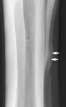
Blunt trauma to bone can lead to subperiosteal hemorrhage, resulting in lifting of the periosteum away from the bone. This process may stimulate the production of periosteal new bone (Figure 15-1). Some bones, such as the second and fourth metacarpal and metatarsal bones, seem particularly prone to such reactions. There is individual variation among horses in susceptibility to such reactions. Usually a lag period of at least 14 days occurs between trauma and the radiological detection of periosteal new bone. Such bone usually is much less dense than the parent bone; therefore soft exposures (or low kilovoltages) are essential for detection of this bone, which initially has a rather irregular outline. As the bone gradually consolidates and then models, it becomes more opaque and more smoothly outlined. Curiously, although a well-established splint exostosis would be expected to become inactive, many have increased radiopharmaceutical uptake (IRU) compared with the parent bone if examined scintigraphically.

Fig. 15-1 Dorsomedial-palmarolateral oblique radiographic image of the metacarpal region. Soft tissue swelling overlies periosteal new bone (arrows) on the middiaphyseal region of the second metacarpal bone.
Periosteal new bone can also develop as a result of fracture, infection, inflammation, and neoplasia. Inflammation of the interosseous ligamentous attachment between the second metacarpal bone and the McIII or the fourth metacarpal bone and the McIII caused by movement and loading can result in periosteal new bone formation and a splint exostosis. It is curious that some of these formations develop rapidly without associated pain, whereas others can cause persistent pain and lameness for many weeks, despite a similar radiological appearance. The bony protuberances that develop on the proximolateral aspect of the metatarsal regions, often bilaterally, are even more enigmatic. They are rarely associated with clinical signs, although they often have IRU despite having been present for several years.
Endosteal New Bone
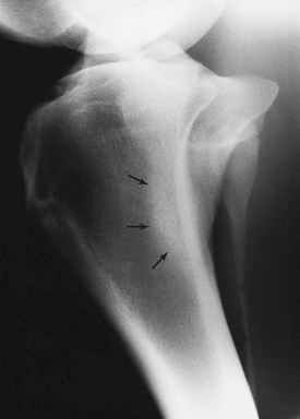
Endosteal new bone may develop as a result of trauma (e.g., a cortical or subcortical fracture or trauma at an enthesis) or inflammation, infection, or, less commonly, a tumor (Figure 15-2). Stress fractures of the dorsal cortex of the McIII are accompanied by the development of endosteal new bone, which may be more readily detected than the fracture itself.
Sclerosis
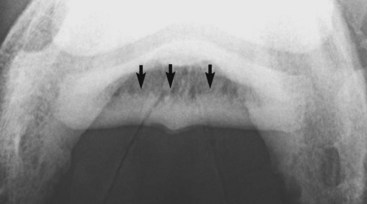
Sclerosis is the localized formation of new bone within bone and results in increased bone mass. It is most easily identified in trabecular bone (Figure 15-3) and occurs in response to several stimuli, including the following:

Fig. 15-3 Palmaroproximal-palmarodistal oblique radiographic image of a navicular bone. The flexor cortex is thickened, and there is extensive endosteal new bone (arrows) resulting in increased radiopacity of the spongiosa.
Enostosis-like lesions are the development of bone within the medullary cavity or on the endosteum, resulting in a relatively opaque (sclerotic) area of variable size. They frequently occur adjacent to the nutrient foramen, and the origin is unclear. They may develop as a focal or multifocal lesion. They vary in size and generally are seen in the diaphyseal regions of long bones in the horse. These lesions have been seen most frequently in the humerus, the radius, the tibia, the McIII, the third metatarsal bones, and the femur. When these lesions develop, they have focal intense IRU and may be associated with pain and lameness. However, they also are seen as incidental findings.
Small focal opacities in the proximal metaphyseal region of the tibia have been seen. The origin and clinical significance are not known. Care must be taken in the fetlock region not to misinterpret the radiopacity caused by the ergot as an opaque lesion within the proximal phalanx.
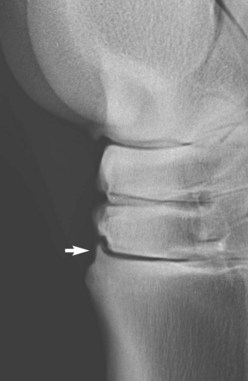
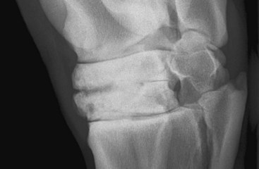
Osteophyte Formation
An osteophyte is a spur of bone on a joint margin that develops as a result of a variety of stimuli, including joint instability, or in association with intraarticular disease, particularly osteoarthritis. Not all periarticular modeling changes at the junction of the articular cartilage and periarticular bone are associated with ongoing joint disease, but radiological differentiation between a subclinical osteophyte and a clinically significant one is difficult. Small spurs frequently are seen on the dorsoproximal aspect of the third metatarsal bone close to the tarsometatarsal joint. Some are quiescent, unassociated with articular pathological findings, whereas others are progressive. Small spurs on the dorsoproximal aspect of the middle phalanx are frequent incidental findings in Warmblood breeds. Mature horses with offset- or bench-knee conformation frequently have spurs on the lateral aspect of the antebrachiocarpal joint without associated clinical signs.
The time of development of an osteophyte after stimulus varies depending on the inciting cause and individual variation. Two weeks to several months may pass before an osteophyte may be identified radiologically. A smoothly marginated osteophyte of uniform opacity is more likely to be long-standing, whereas a poorly marginated osteophyte with a lucent tip is likely to be active.
Some joints seem to have a greater propensity than others for the development of periarticular osteophyte formation. The reason for this tendency is unknown and may in part reflect the ease with which osteophytes can be detected radiologically. Even within what is currently considered a single disease process, osteoarthritis of the distal hock joints (bone spavin), some horses develop predominantly periarticular osteophytes (Figure 15-4), whereas others have narrowing of the joint space and subchondral sclerosis. A third group develops extensive radiolucent areas (Figure 15-5).

Fig. 15-4 Lateromedial radiographic image of a hock. There is a moderately sized periarticular osteophyte on the dorsoproximal aspect of the third metatarsal bone, close to and traversing the tarsometatarsal joint (arrow).

Fig. 15-5 Dorsolateral-plantaromedial oblique radiographic image of a hock. There is narrowing of the centrodistal joint space. Radiolucent regions are seen in the subchondral bone of the central and third tarsal bones dorsomedially. There is loss of trabecular architecture because of medullary increased radiopacity in the central and third tarsal bones. Note also the osseous cystlike lesion in the distal dorsomedial aspect of the third tarsal bone.
Enthesophyte Formation
Enthesophyte formation is new bone at the site of attachment of a tendon, ligament, or joint capsule to bone. Entheseous new bone reflects the bone’s response to stress applied through these structures, such as ligamentous tearing or capsular traction (Figure 15-6

Stay updated, free articles. Join our Telegram channel

Full access? Get Clinical Tree

