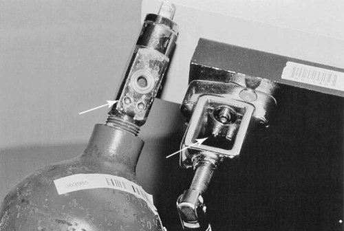
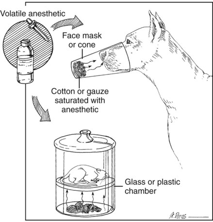
I Compressed gases: O2, N2O, and other select gases come in color-coded cylinders of varying size (Tables 12-1 and 12-2). O2 is used as the carrier gas for delivering inhalant anesthetics in most anesthetic circuits TABLE 12-1 Psi, Pounds per square inch; STP, standard temperature and pressure. TABLE 12-2 United States and IOS (International Organization For Standardization) Gas Color Codes A Cylinders should be handled carefully 1. Never leave an unsupported or unsecured cylinder sitting upright a. Store E cylinders in a rack b. Secure H cylinders anchored to a wall or a transport cart with a chain 2. A cylinder may explode if dropped because it is under high pressure 3. Open cylinder valves slowly and completely 4. Crack the cylinder valve (open and shut quickly) before attaching it to the machine to remove dust from the connecting port (dirt or dust plus rapid compression at the connecting port can cause a fire) 5. Install a new gasket when connecting each full cylinder to the connecting port B Most veterinary and human anesthetic machines have a hanger yoke for attaching one or more E cylinders; hanger yokes and E cylinders are keyed (coded) with a pin index safety system to prevent inadvertent connection of the wrong cylinder to the wrong gas yoke on the anesthetic machine (Fig. 12-1) C Centralized O2 sources usually use G or H cylinders 1. H cylinders require an individualized pressure regulator (thread size and connection are coded for different types of gas) 2. These cylinders are attached to the machine by a length of high-pressure hose connected to the Diameter Index and Safety System fitting of the machine 3. In some older systems, the high-pressure hose is connected to a special yoke-block connector that attaches to the pin index system in the hanger yoke 1. O2 is present within the cylinder only as a gas, and its pressure is proportional to gas volume 2. N2O is present within the cylinder as a liquid and a gas E Oxygen generators can be installed for central gas supply; they extract O2 from the environment (air: 20% O2) to produce 90% to 95% O2 II Hanger yoke site for E cylinder (see Fig. 12-1) A Pin index system configuration avoids improper cylinder connection B A brass filter prevents particulate contamination of the anesthetic machine’s gas lines C Pressure gauges are located on the anesthetic machine or attached directly to the cylinder display cylinder pressure D One-way (check) valves prevent transfilling of adjacent cylinders or loss of O2 from the cylinder into the pipeline supply III Pressure-reducing valves (pressure regulators) are built into most anesthetic machines or can be attached directly to the cylinder A Pressure-reducing valves reduce the pressure within the cylinder to a constant outlet pressure of about 50 psi B Provide constant pressure to the flowmeter C Allow a wide range of gas flow (L/min; mL/min) settings D Ensure that the flowmeter does not have to operate at high pressures E Hospital supply cylinders (G and H) require individualized regulators A Many but not all anesthetic machines incorporate an O2 “fail-safe” system: if the O2 supply is interrupted, N2O and any other gas flow is automatically interrupted B An audible O2 supply failure alarm also activates on some machines C Not all machines are so equipped, which means if the O2 supply is interrupted, N2O may be delivered without O2 A A flowmeter controls the rate at which a specific gas (e.g., O2) is delivered (milliliter per minute, liter per minute). The most common gas flowmeter is the rotameter. 1. Flowmeters contain a ball or bobbin that rises within a tapered glass tube to a height proportional to the flow of gas through the tube. The gas flow rate is read at the widest diameter of the ball or bobbin. B Ideally, the O2 flowmeter should be the last in a series of flowmeters (a hypoxic gas mixture is less likely to develop if a flowmeter tube is cracked) C Avoid excessive torque (twisting) when closing flowmeters, because the knobs can come to be out of adjustment or be twisted off D Flowmeter tubes are gas-specific; an N2O flow tube cannot be substituted for an O2 tube E Individual gas flows are combined downstream from the flowmeters; from there, gases move to an out-of-circuit vaporizer or directly to the anesthetic circuit F Some machines are equipped with two O2 flowmeters A Diverts O2 past the vaporizer and delivers O2 directly to the common gas outlet or anesthetic circle B Delivers O2 rapidly to the circle at 35 to 75 L/min VII Common gas outlet: the point-of-gas-exit from the machine for O2, N2O, and vaporized (out-of-circuit) anesthetic gas. It has a 15-mm connector. A Vaporizers are designed to volatilize liquid inhalant anesthetic drugs and to deliver clinically useful concentrations of anesthetic vapor B Anesthetic machine vaporizers are located near the flowmeters and can be either out (vaporizer out of the circuit [VOC]) or in (vaporizer in the circuit [VIC]) the anesthetic breathing circuit 1. Precision VOC vaporizers deliver precise anesthetic concentrations (%) of anesthetic vapor that are relatively independent of temperature and fresh gas flow rate; the manufacturer specifies limits of temperature and flow 2. Gas flow within the vaporizer is split between a bypass and vaporization chamber a. The splitting ratio between these two chambers depends on the saturated vapor pressure of the anesthetic and the desired output (%) of anesthetic vapor 3. Precision VOCs are agent-specific (1) Tec 6 vaporizer (Ohmeda): electronically heated vaporizer; unique construction because of the physical-chemical properties of desflurane 4. VICs (also called draw-over vaporizers): the concentration delivered is temperature and flow dependent a. Draw-over vaporizers are not agent-specific b. Output depends on the following: (1) The inhalant anesthetic’s volatility: less volatile agents (e.g., ether) require a wick; current inhalant anesthetic drugs (isoflurane, sevoflurane) need no wick (2) Temperature: vapor pressure and therefore vaporizer output increases or decreases with ambient temperature (3) Overdose can occur at high ambient temperatures (4) Animals may be difficult to keep anesthetized at low ambient temperatures (1) Controlled by animal’s minute ventilation; increases in depth and rate of ventilation (spontaneous or assisted) increase the vaporizer output (1) Wick versus no wick; adjustable sleeves; distance between the surface of the liquid and the gas flow e. Location of vaporizer in the breathing circuit (1) The vaporizer should be mounted on the inspiratory side to reduce the condensation of water in the vaporizer f. Calibration marks on top of the vaporizer do not indicate the percentage output of VIC vaporizers (1) Ohio No. 8 Vaporizer (Pitman-Moore); wick must be removed when using with isoflurane or sevoflurane (2) Stephens (Henry Schein); wick must be removed when using with isoflurane or sevoflurane h. Maintenance: wick should be allowed to dry weekly to rid system of excess water vapor 1. Vaporizers should be filled with anesthetic in a well-ventilated area at the beginning or end of the day to minimize exposure of personnel to vapor 2. Vaporizers must be in the off position when filling or draining 3. Special filling devices are available to minimize spills and escape of vapors into the environment 4. Vaporizers should not be tilted or laid on their sides unless completely drained; dangerously high concentrations can result during subsequent use A Open drop or cone system (Fig. 12-2) B Nonrebreathing valveless systems (Mapleson classification) rely on relatively high, fresh gas flow rates (Table 12-3) to remove CO2. The following classifications are based on the location of fresh gas inlet and opening (or valve) for exit of exhaled gas. The relative location of the fresh gas inlet and the valve opening determine the efficiency of the circuit. TABLE 12-3 Recommended Oxygen Flow Rates for Anesthetic Systems
Anesthetic Machines and Breathing Systems
Overview
Anesthetic Equipment
CYLINDER SPECIFICATION (liters, STP)
Agent
E (8.8 cm × 66 cm)
G (17.6 cm × 121 cm)
H (19.8 cm × 121 cm)
Filling Pressure (psi)
Oxygen
655
5290
6910
2200
Nitrous oxide
1590
12,110
14,520
750
Carbon dioxide
1590
4160
800
Helium
500
4350
5930
1650

Gas or Function
United States
IOS
Oxygen
Green
White
Nitrous oxide
Light blue
Light blue
Medical air
Yellow
Black and white
Suction
White
Yellow
Nitrogen
Black
Black
Carbon dioxide
Gray
Gray
Helium
Brown
Brown
Anesthetic Breathing Systems
NONREBREATHING SYSTEMS
Mapleson systems*
Magill system
100 mL/kg/min
Lack system
150 mL/kg/min
Ayre’s T piece
150 mL/kg/min
Bain circuit
150 mL/kg/min
Insufflation
200-300 mL/kg/min
REBREATHING OR CIRCLE SYSTEMS
Closed
3-5 mL/kg/min†
Semi-closed low flow
5-10 mL/kg/min‡
Semi-closed high flow
20-30 mL/kg/min‡ ![]()
Stay updated, free articles. Join our Telegram channel

Full access? Get Clinical Tree


