Fig. 1.
Radiometabolites of [11C]-WAY-100635 after labelling in the 2-methoxy position or in the carbonyl of the amide group.
In addition, the pharmacokinetics of the radiotracer and the biological process under study need to be compatible with the half-life of the isotope. For example, for blood flow measurements, it is preferable to use [15O]-water (half-life t 1/2 = 2 min) which enables repetitive injections within a short period of time. In contrast, when studying slower biological processes like receptor binding or metabolism, it is preferable to select a radionuclide with a longer half-life, such as fluorine-18 (t 1/2 = 110 min), allowing longer acquisition times. In vivo follow-up studies of larger biomolecules, such as peptides and/or antibodies with slow kinetics, need radioisotopes with very long half-lives, such as copper-64 (t 1/2 = 12.7 h) or iodine-124 (t 1/2 = 4.2 day).
2.1.2 Production of the Radionuclides
Table 1 lists some of the positron emitters and their half-lives, main mode of production and positron energies.
Table 1
Main characteristics of some position emitting isotopes
Isotope | Half-life (min) | Production mode | Maximum β+ energy (MeV) | Maximal free path in water (mm) |
|---|---|---|---|---|
[18F] | 110 | 18O(p,n)18F | 0.64 | 2.3 |
[11C] | 20 | 14N(p,α)11C | 0.96 | 3.9 |
[15O] | 2 | 15N(p,n)15O | 1.72 | 8.0 |
[13N] | 10 | 16O(p,α)13N | 1.20 | 5.1 |
[76Br] | 960 | 75As(3He,2n)76Br | 3.70 | 19.0 |
[124I] | 6,048 | 124Te(p,n)124I | 1.50 | 7.0 |
A major constraint of positron-emitting nuclides is the very short half-life of most isotopes which necessitates an onsite production. An exception to this is fluorine-18 which, with a half-life of almost 2 h, can be distributed to centres up to several hundred kilometres away. In addition, this relatively long half life allows a more sophisticated radiochemistry and its position weak energy (635 keV maximum) represent a good point in terms of desimetry to clinical applications.
The radionuclides are produced in a cyclotron consisting of five major components: an ion source, a magnet, a radiofrequency switching circuit, an ion beam extractor and a target. The ion source provides an electrical discharge across a volume of gas-generating ions, e.g. negative hydrogen ions, which are constrained into a spiral orbit by a uniform magnetic field. The ion beam is subsequently accelerated by an alternating electric field in order to increase the energy of the ions. Once the beam reaches sufficient energy, it passes through a thin carbon foil that strips the electrons from the ions, yielding an energized beam of protons that is used to irradiate a target of non-radioactive atoms. Depending on the target, various radionuclides can be produced, as outlined in Table 1.
2.1.3 Radiosynthesis
Four main considerations need to be taken into account when using short-lived β+-emitting isotopes: the reaction time factor, the dilution factor, the radiation protection and the labelling precursor.
The reaction time factor. First, it is preferable to choose a radiosynthesis scheme with the shortest reaction time possible, such as the one-step labelling. If this is not feasible, the isotope has to be introduced during the very last steps of the preparation of the radioligand. Second, the purification method should be as efficient as possible using ideally solid-phase extraction (SPE) cartridges and/or a semi-preparative high-performance liquid chromatography (HPLC). Finally, the quality control system, which assures the radionuclidic and chemical purities, as well as the sterility and pyrogenicity of the radiotracer, should be robust and rapid. Overall, the maximum preparation time for the radiotracer (including quality control and syringe preparation) should not exceed 2–3 times the radioactive half-life of the positron emitter selected for the study.
The dilution factor. The quantity of the primary precursors produced by the cyclotron is very low (order of nanomolar) in contrast to the quantity of labelling precursor (order of micromolar). As a consequence of the stoichiometry, the conversion rate is high and the radioactive reagent is consumed very rapidly producing high radiochemical yields within a short time. The small amounts of precursors require, thus, the use of high-quality reagents and a high clean status of equipment. For example, atmospheric carbon dioxide contamination should be avoided when recovering [11C]-carbon dioxide from the cyclotron to reach the highest possible specific activity (Bq/mol). On the other hand, the advantage from a technical point of view is the simplified technical handling, e.g. by using smaller chemical units and reactors.
Radiation protection. Radiochemical syntheses are performed in fully automated chemical-processing units, in which the radionuclide is brought together with the appropriate reagents and with the labelling precursor to produce the radiotracer. In addition to an automated radiosynthesis, the chemical units minimize the radiation dose received by the radiochemists (Fig. 2).
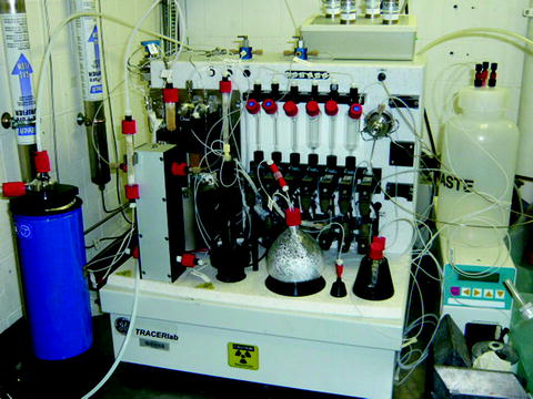
Fig. 2.
An automated chemical unit designed for carbon-11 methylation reactions.
The labelling precursor. This is chosen in function of its reactivity with the primary or secondary precursors, and having access to various labelling precursors is crucial for radiotracer synthesis.
2.1.4 Reaction Schemes
Carbon-11
The ubiquitous presence of carbon makes carbon-11 an attractive and important positron-emitting isotope. However, it is beyond the scope of this chapter to describe extensively carbon-11 radiochemistry and for review the reader is referred to Allard et al. (2). The most commonly applied production method to obtain carbon-11 is the 14N(p,α)11C nuclear reaction. If the target of the cyclotron is filled with a nitrogen/oxygen gas mixture, [11C]-carbon dioxide is produced (blue box, Fig. 3), whereas when a nitrogen/hydrogen gas mixture is present, [11C]-methane is recovered (green box, Fig. 3). [11C]-carbon dioxide and [11C]-methane are referred to as primary precursors. As [11C]-methane is unable to react directly with the labelling precursor, subsequent rapid reactions are needed to produce more reactive molecules, referred to as the secondary precursors. These react with the labelling precursor yielding the final radiotracer. Even though [11C]-carbon dioxide has very reactive properties, it can be transformed in secondary precursors for some chemical reactions, e.g. the methylation and carbonylation reaction (Fig. 3).
Fig. 3.
Representation of the main reaction types used for the incorporation of carbon-11 in molecules of interest, starting from the two [11C] primary precursors and some of the main secondary precursors.
[11C]-carbon dioxide as the primary precursor:
1.
The most frequently used reaction is [11C]-methylation (red box, Fig. 3) using [11C]-carbon dioxide as primary precursor and [11C]-methyl iodide (I[11C]-CH3) and [11C]-methyl triflate ([11C]-CH3OTf) as secondary precursors (3). For example, [11C]-flumazenil (4) and [11C]-raclopride (5) can be generated through this chemical pathway.
2.
Palladium-catalyzed reactions can be considered as an indirect [11C]-methylation reaction (pink box, Fig. 3). The secondary precursor [11C]-methyl iodide allows for example, the synthesis of the two radioligands of the metabotropic glutamate receptor (mGluR5) antagonists, the [11C]-M-MTEB via a Suzuki cross-coupling reaction (6) and the [11C]-MPEP via a Stille reaction (7).
3.
Reaction of [11C]-carbon dioxide with Grignard reagents (dark blue box, Fig. 3) can form [11C]-carboxylic acids or the more reactive acid chloride species. A further treatment of this acid chloride with amines leads to [11C]-amides. This route is one of the two synthesis pathways used to label the [11C]-WAY-100635 on the carbonyl group (8).
4.
Finally, the [11C]-carbonylation reaction using [11C]-carbon monoxide as the secondary precursor (light blue box, Fig. 3) (9) allows access to imides, ketones, amides and acrylamides. For example, (S)-[11C]-PK11195, the reference ligand for peripheral benzodiazepine receptor (PBR), can be obtained via this reaction (10).
[11C]-methane as the primary precursor:
1.
[11C]-methane allows the production of the highly reactive secondary precursor, the [11C]-phosgene molecule ([11C]-COCl2) (green box, Fig. 3). The potent, reversible and competitive mono-amine oxidase-A (MAO-A) inhibitor, [11C]-befloxatone, is for example, obtained via this route (11). Recently, a simplified [11C]-phosgene preparation method has been proposed (12).
2.
[11C]-methane reacts with ammoniac over platinum to produce the [11C]-hydrogen cyanide ([11C]-HCN) which is the starting material for [11C]-cyanation reactions (orange box, Fig. 3) (13). This secondary precursor can be used directly to synthesize amino acids (14) or can be transformed in another secondary precursor, the [11C]-CuCN, to obtain, for example, the mGluR5 antagonist [11C]-LY2232645 (15).
Fluorine-18
An important difference between carbon-11 and fluorine-18 radiochemistry follows from the limited chemical methods that are available to incorporate fluorine-18 into the target molecule, which is in contrast to carbon-11 radiolabelling. It is beyond the scope of this chapter to describe extensively fluorine-18 radiochemistry and for a review of this domain the reader is referred to the recent special issues 2 and 3 of the volume 3, edited in 2010 by Current Radiopharmaceuticals (16–18).
Briefly, two main reactions are used: electrophilic and nucleophilic radiofluorination. The first method uses molecular [18F]-fluorine ([18F]-F2) generally obtained via the 20Ne(d,α)18F nuclear reaction or more recently via the 18O(p,n)18F reaction, where the cyclotron target is filled with 18O gas. These two nuclear reactions involve an exchange step between carrier non-radioactive fluorine and [18F]-fluorine, inducing a poor specific radioactivity. The second radiofluorination uses the anion [18F]-fluoride. This method is more selective and provides significantly higher yields and specific radioactivities than the electrophilic radiofluorination. Therefore, nucleophilic radiofluorination is often preferred, particularly for brain imaging studies, where high-specific radioactivities are required.
Electrophilic radiofluorination. [18F]-fluorine is not the only electrophilic-labelling reagent used for this reaction. It is sometimes suitable to involve less-reactive fluorinating reagents, such as trifluoromethyl-[18F]-hypofluorite (CF3O[18F]-F) (19) or acetyl-[18F]-hypofluorite (CH3CO2[18F]-F) (20). The labelling precursor, consisting of a nucleophile entity such as an alkene, an enol or an organostannyl compound, is then radiolabelled with one of these [18F] electrophilic reagents to produce the [18F]-radiotracer. Starting from [18F]-fluorine and the 6-trimethylstannyl-labelling precursor, the 6-[18F]-fluoro-l-DOPA can be obtained using a fully automated computer-controlled module (TRACERlab FXFDOPA™, GE Medical Systems) (21).
Nucleophilic radiofluorination. As previously mentioned, this method is the most efficient and allows significantly higher yields and specific radioactivity than the electrophilic radiofluorination reaction. The anion [18F]-fluoride, recovered after an 18O(p,n)18F nuclear reaction, is highly soluble in liquid [18O]-water, which served as a the target for the nuclear reaction. However, the [18F]-fluoride is a strong base, but a poor nucleophilic reagent. The most efficient and commonly used procedure to increase the nucleophilic force of [18F]-fluoride consists of fixing [18F]-fluoride on an anion exchange resin before eluting it with a diluted aqueous potassium carbonate solution. This creates a chelation between the [18F]-fluoride anion and the potassium cation. This chelation is then weakened using a kryptand, the polyaminoether Kryptofix-222® (4,7,13,16,21,24-hexaoxa-1,10-diazabicyclo[8.8.8]hexacosane). After concentration to dryness, the complex (K-[18F]-F-K222) is often further dried by azeotropic evaporation with acetonitrile. The reactive nucleophile [18F]-fluoride reagent is then dissolved in polar solvents, such as DMSO, DMF, acetonitrile or bulky alcohols (22). Typical reaction conditions involve high reaction temperatures, between 80 and 200°C, and even microwave irradiations. In general, the reaction time lasts a few minutes to half an hour. Depending on the target molecule, being an aliphatic or aromatic entity, the nucleophilic radiofluorination occurs by direct or indirect nucleophilic fluorination.
Direct nucleophilic fluorination (left side, Fig. 4) is the method of choice to radiolabel a target molecule with a fluorine-18 because it consists of a one-step process by direct reaction of the radioactive precursor, [18F]-fluoride, with the labelling precursor. Within direct fluorination, short reaction steps (one to two reactions) can be considered as well, e.g. to remove a protective or to remove/transform a strong electron-withdrawing group.
Fig. 4.
Direct and indirect nucleophilic radiofluorination ways in aliphatic and aromatic series.
1.
2.
Direct nucleophilic fluorination is also possible in the aromatic series: The substitution reaction in homoaromatic series (red box, Fig. 4) requires aromatic nuclei carrying both a good leaving group and a strong electron-withdrawing substituent placed para or ortho to the leaving group. The serotoninergic 5HT2A receptor ligand [18F]-altanserin has been obtained via this route (24). Unlike the homoaromatic counterpart, heteroaromatic substitution reaction requires only a good leaving group. The nicotinic cholinergic α4β2 receptor radioligand [18F]-F-A-85380 has been synthesized at a position ortho to the ring nitrogen of the pyridine (25).
Indirect nucleophilic fluorination (right side, Fig. 4) is used when direct nucleophilic fluorination is not feasible due to the relatively harsh reaction conditions, such as high pH and high reaction temperatures, not supported by many labelling precursors.
1.
To overcome this problem, [18F]-indirect aliphatic fluorination reactions (dark blue box, Fig. 4) use prosthetic groups, such as [18F]-alkylating agents (26) and [18F]-alkyne reagents (also developed to radiolabel macromolecules by “click chemistry” (27)). A Radioligands obtained by this reaction scheme is [18F]-LBT-999, a dopamine transporter ligand starting from the (E)-4-[18F]-fluorobut-2-enyl tosylate and the tropane derivative as the labelling precursor (28).
2.
Many other prosthetic groups have been developed to succeed in the indirect aromatic fluorination (light blue box, Fig. 4). Especially, [18F]-fluorobenzene and [18F]-fluorobenzaldehyde derivatives are very convenient prosthetic groups. Notably, the latter is used to produce the 6-[18F]-fluoro-l-DOPA with a specific radioactivity higher than 74GBG/μmol in contrast to the specific radioactivity less than 1GBG/μmol obtained via the electrophilic fluorination route (29).
The increasing interest of macromolecules (green box, Fig. 4) for treatment and diagnosis of disease has contributed to the development of [18F]-fluorine radiolabelling of oligonucleotides, peptides, proteins and antibodies. Many other [18F]-prosthetic groups reacting in a chemoselective way with the macromolecule have, thus, been designed. Two of these most commonly used prosthetic groups are the N-succinimidyl-4-[18F]-fluorobenzoate ([18F]-SFB) (30) and the maleimide 1-[3-(2-[18F]-fluoropyridin-3-yloxy)propyl]pyrrole-2,5-dione ([18F]-FPyME) (31) which react selectively with thiol group of cysteine residues.
2.2 PET Instrumentation
2.2.1 The Physics of PET
The vast majority of annihilation events between positions and surrounding electrons, give rise to the emission of two 511keV photons that are emitted in almost exactly opposite directions (180°), albeit with a directional uncertainty of about ± 0.5° (Fig. 5). This physical particularity yields some uncertainty in the exact determination of the site of annihilation, thereby limiting the spatial resolution of the technique.
Fig. 5.
Annihilation of the positron, resulting in two 511 keV photons that are emitted in almost exactly opposite directions (180°), albeit with a directional uncertainty of about ± 0.5°.
The distance that the positron travels prior to annihilation (free path) is dependent on the initial emission energy and the medium through which it is travelling (Table 1). Depending on the isotope, the mean distance travelled by the positron before annihilation varies, affecting the actual spatial resolution in the images. As a consequence, even if the point of annihilation is very close to the point of emission, the image generated from the distribution of annihilation radiation only approximates the actual distribution of the radionuclide itself.
2.2.2 Coincidence Detection of the Annihilation Events
The detection of the positron emission is achieved by the simultaneous (coincident) detection of the two collinear 511 keV photons resulting from the annihilation process by two opposite detectors surrounding the positron-emitting object. Surrounding the subject’s head by a large number of detectors (up to 20,000 for the most recent tomographs) permits a multi-coincidence detection and a spatial reconstruction of the various annihilation events (Fig. 6).
Fig. 6.
Detector configurations: Circular set-up (a, b), polygonal array set-up (c), partial detector rings (d), Anger camera systems (e).
Typically, in a circular set-up, each detector is placed in coincidence with about half of the total detectors in the ring (Fig. 6a, b), whereas in a polygonal array set-up the detector is in coincidence with the opposed detector bank (Fig. 6c). PET systems with only partial detector rings are less expensive, but require rotation of the detector assembly round the longitudinal axis of the patient to complete the acquisition of the projection data (Fig. 6d). Continuous, large-area detectors, such as those found in multi-head Anger camera systems and used for single-photon emission-computed tomography (SPECT), have now been appropriately modified and are as well used as for coincidence imaging of positron emitters (Fig. 6e).
Each coincidence event, i.e. simultaneous detection of a photon pair within a time window of a few nanoseconds, represents a line in space, the Line of Response (LOR), connecting the two detectors along which the annihilation process occurred. The raw data collected by a PET scanner are, thus a list of “coincidence events” representing near-simultaneous detection of annihilation photons by a pair of opposite detectors. It takes approximately 3 ns for photons to traverse the field of view of a PET scanner, and in addition to measure the position of arriving annihilation photons, the detectors placed in coincidence also measure their time of arrival. Each detected photon is, thus, tagged with a detector position and a detection time: if the detection time difference between two photons is smaller than the coincidence window (traditionally 5–10 ns), the two events are considered to be physically correlated to the same annihilation event (Fig. 7). Time-of-flight PET uses this time-of-flight difference between the detection of the two photons to better locate the annihilation position of the emitted positron along the LOR (for review, see Conti et al. (32)).
Fig. 7.
Line of response and representation of a true coincidence.
Besides true coincidence events arising from single positron annihilation followed by detection of the photon pair without any precedent interaction of the photon pair with the medium (solid line in Fig. 8a), two other major events might cause coincidences. Scattered coincidence (solid line in Fig. 8c) results from a single annihilation with one of the photons (dashed line) undergoing a change in direction (due to the Compton scatter effect) in the medium before detection. Though a true incidence, the LOR is displaced and thus degrading image contrast and resolution. In addition to true coincidences, random or accidental coincidence events (Fig. 8b) occur when two photons not arising from the same annihilation event (dashed lines) are detected by two opposite detectors within the coincidence time window of the system. These falsely detected coincidences (full lines) are uniformly distributed in time and will cause isotope concentrations to be overestimated if not corrected for. Photons are inherent to attenuation as well, reducing the number of coincidences and thus underestimating the amount of radioligand within a region of interest, if not corrected for. Although the magnitude of this correction for small animal subjects is much smaller than for humans (1.3 for a 3-cm diameter set-up in mouse versus 1.6 for a 5-cm diameter in rat versus 45 for a 40-cm diameter in human), it is important to correct the data for attenuation in order to obtain accurate quantitative images of the tracer distribution (33).
Fig. 8.
Different types of coincidences: True (a), random (b) and scattered (c).
In conclusion, in order to achieve quantitative images, the acquired data need to be corrected for random, scattered and attenuation effects during the image reconstruction process. Random coincidences are usually subtracted by the delayed coincidence method while scatter subtraction is based on model calculation. Correction for photon attenuation is by far the most important correction, especially on large animal brains.
2.2.3 Attenuation Correction
A significant fraction of the photons arising from annihilation events fail to reach the detectors due to their auto-attenuation in the body. In addition, at the surface of the body, the mean attenuation is less, as the LOR passes mostly through air. These differences in attenuation will result in distortions in the reconstructed image if not corrected for. If the anatomical properties of the subject/object are known, the measurement along each LOR can be corrected for the attenuation effect. Several methods of correcting for attenuation in PET exists: the material properties of the object/subject can be obtained using an external rotating pin single photon-emitting source, e.g. [68Ge] or [57Co], or by using an X-ray-computed tomography scanner (for more information, the reader is referred to Fahey et al. (33)). In this case, the attenuation coefficients are scaled to the appropriate energy (511 keV) using tabulated values. The attenuation map is then projected along each LOR to give the attenuation coefficient of the coincidences.
2.2.4 Detector Design
Detectors for annihilation radiation should have good stopping power for 511 keV photons and the ability to resolve the time of arrival of incident photons within a few nanoseconds at most. Additionally, because these detectors are configured without collimators, they must be capable of operating in high photon flux environments. These extreme conditions have led to the development of specialized detectors. The most important practical features of scintillation detectors include a high mass density and a high effective atomic number to maximize the crystal stopping power. In addition, a fast crystal (short scintillation decay time) allows the use of a narrow coincidence window and therefore a notable reduction of the random coincidences count rate. Finally, the detector system should have a good energy resolution to reduce the fraction of detected scattered gamma rays as much as possible. Typical choices are bismuth Germinate (BGO), which has excellent stopping power, or lutetium oxyorthosilicate (LSO), which has good stopping power and excellent signal speed. Another choice is gadolinium silicate (GSO), which has intermediate stopping power but excellent signal speed and also offers improved energy resolution (Table 2).
Table 2
Properties of different solid scintillation detectors
Material | Density (g/cm3) | Atomic number | Decay time (ns) |
|---|---|---|---|
NaI (TI) | 3.76 | 11, 53 | 230 |
BGO | 7.13 | 83, 32, 8 | 300 |
LSO | 7.4 | 71, 32, 8 | 40 |
GSO | 6.71 | 64, 32, 8 | 60 |
Csi (TI) | 4.51 | 55, 53 | 1,000 |
2.2.5 Commercially Available Preclinical PET Scanners
While the first generations of PET tomographs were characterized by limited resolution and sensitivity, the latest generation of PET scanners combines a relatively high spatial resolution, a high sensitivity with a large field of view resulting in better counting statistics and improved region-of-interest definition due to decreased partial volume effects. Table 3 gives a brief overview of the main characteristics of several commercially available PET imaging systems.


Table 3
Properties of Preclinical PET scanners
FOV (cm) | Resolution FWHM (mm) | Sensitivity (threshold) | Attenuation correction method | Crystal | Scintillation detector | Manufacturer | ||
|---|---|---|---|---|---|---|---|---|
Transaxial | Axial | |||||||
Triumph™ | 3.7/7.5 | 11.6 | 0.9 | 2/4% | CT | LYSO/LGSO | APD | Gamma Medica-Ideas |
MOSAIC | 12.8 | 11.6 | 2.7 | 1.3% (400 keV) | Cs-137 | GSO | PMT | Philips |
FOCUS 220 | 7.6 | 19 | 1.4 | 4% | Ge-68; Co-57 | LSO | PSPMT | Siemens |
FOCUS 120 | 10 | 7.6 | 1.3 | 6.5 (250 keV) | Ge-68 | LSO | PSPMT | Siemens |
INVEON | 10 | 12.7 | 1.4 | 10% (100 keV) | Co-57; CT | LSO | PSPMT | Siemens |
eXplore Vista | 6 | 4.6 | 1.6 | 4% (250 keV) | Ge-68 | LYSO-GSO | PMT | GE Healthcare |
ClearPET | 13/30 | 11 | 1.48 | 3.2% (350 keV) | ns | LYSO-LuYAP | PSPMT | Raytest |
HIDAC | 17 | 28 | 1.0 | 1.8% (200 keV) | ns | Position sensitive gas ionisation chamber | Oxford Positron systems | |
SHR-7700 | 33 | 16.3 | 2.6 | ns | Ge-68 | BGO | PMT | Hamamatsu Photonics KK |
Stay updated, free articles. Join our Telegram channel
Full access? Get Clinical Tree
