Fig. 1
Schematic drawing of the pressure myograph setup used for the described protocols
1.
Regular microscope.
2.
Micro-forceps, micro-scissors, and petri dish for dissection.
3.
Glass pipettes with an outer tip diameter of 80–200 μm (at least 20 μm smaller than the mounted artery’s internal diameter).
4.
Monofilament nylon sutures (15-μm diameter).
5.
Pressure myograph (e.g., model 110P, Danish Myo Technology, Aarhus, Denmark).
6.
Two pressure columns (up to 150 mmHg) mechanically adjusted or an interface with buffer-filled containers (e.g., 110P, Danish Myo Technology, Aarhus, Denmark).
7.
Computer and software: frame grabber and dimension-analyzing program (e.g., Vessel View, Danish Myo Technology, Aarhus, Denmark).
8.
Inverted microscope, magnification × 100 (e.g., Telaval 31, Zeiss, Oberkochen, Germany).
9.
Video camera.
10.
A graphic writer is optional to record the pressure and diameter outputs and found useful in teaching students the setup.
11.
Electric thermometer.
12.
2 × 50-ml syringes without pistons, attached to the pressure columns. These syringes represent the inflow and outflow reservoirs in Fig. 1.
13.
Silicone tubing (1 mm in diameter, Danish Myo Technology, Aarhus, Denmark) for myograph setup.
14.
Two 3-way valves connected to each end of the pressure myograph.
15.
Air mixture of 95 % O2 and 5 % CO2.
16.
Roller pump (e.g., Alita Watson Marlow 400, VS2-10R-Midi, 2.5–50 rpm).
17.
Roller pump tubing (e.g., Gilson, gas-tight PVDF), different sizes adequate for the given artery diameters, roller pump, and wanted flow levels.
18.
Physiological saline solution, 1.6 mM calcium (PSS1,6): 1.6 mM CaCl2, 119 mM NaCl, 4.7 mM KCl, 5.5 mM glucose, 7.0 mM MgSO4, 25 mM NaHCO3, 1.18 mM KH2PO4, and 0.026 mM ethylenediaminetetraacetic acid (EDTA).
19.
Physiological saline solution, 0.0 mM calcium (PSS0,0): composition as PSS1,6 but without CaCl2 and with 0.1 mM ethylene glycol tetraacetic acid (EGTA) instead of EDTA.
20.
Thromboxane analogue 9,11-di-deoxy-11α, 9α-epoxymethanoprostaglandin F2α (U46619).
21.
Acetylcholine.
22.
Papaverine.
23.
Acetic acid.
24.
Demineralized water.
3 Methods
3.1 Mounting
The mounting procedure is conducted under a regular microscope.
1.
Fill pressure myograph tubing, chamber, and roller pump tubing with 4 °C PSS1,6 (see Note 1 ) and set pressure to 0 mmHg.
2.
Advance the outflow pipette so that the tips of the outflow and inflow pipettes are barely touching each other. The pipettes are aligned and the distance on the micrometer gauge is noted (see Note 2 ). Retract again the outflow pipette.
4.
Transfer the isolated artery to the chamber of the pressure myograph.
7.
Cut the distal end of the artery to produce an arterial segment of 1.5–3 mm of length (see Note 6 ).
8.
Raise the pressure of the inflow pipette to 20–25 mmHg to wash out the remaining blood in the artery. Afterwards the pressure is lowered to 0 mmHg again (see Note 7 ).
9.
Advance the outflow pipette toward the inflow pipette to allow cannulation of the distal end of the artery without stretching it.
10.
Cannulate the distal end of the artery with the outflow pipette and tighten two of the sutures around the vessel and pipette (see Note 5 ).
11.
Raise the pressure to 30 mmHg, remove the PSS1,6 by suction, and inspect the artery through the microscope to identify leaks (see Note 8 ).
12.
Refill the chamber with 5 ml 4 °C PSS1,6.
13.
Close the 3-way valve on the outflow side of the set up (Fig. 2a). Pressure should henceforth be managed from only one side at a time (see Note 9 ).
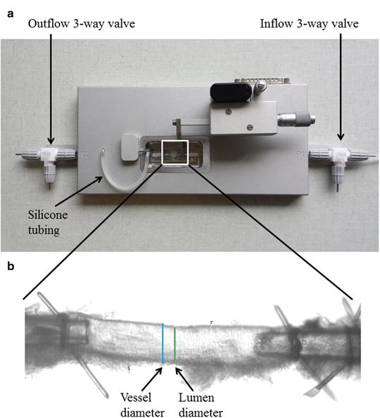
Fig. 2
(a) Pressure myograph (P110) used for functional and structural studies. The inflow and outflow 3-way valves as well as the silicone tube in between the pressure transducer and the mounting pipette. This silicone tubing can be used to administer drugs intraluminally (see Subheading 3.3). (b) Mouse left anterior descending coronary artery (ID ~120 μm) mounted on two glass micropipettes in a pressure myograph for structural measurements. Bars show outer diameter (vessel diameter) and inner diameter (lumen diameter). It is important that the adhering myocardium is carefully removed before mounting
14.
Place the pressure myograph lid over the myograph chamber and connect an air tube to the air connection in the lid. The myograph bath is henceforth bubbled with an air mixture of 95 % O2 and 5 % CO2.
16.
Raise the pressure to 60 mmHg while stretching the artery to avoid bulging.
17.
Stretch the arterial segment longitudinally to 110 % of its passive, non-bulging length.
18.
Transfer the chamber with the artery to the inverted microscope and turn on the light and video camera.
19.
Adjust the frame grabber on the computer of the pressure myograph setup to continuously monitor the internal diameter (see Note 11 ).
20.
Turn on the graph writer. This will continuously monitor the internal diameter and median pressure over the artery at 3 Hz, correlating to the numeric registrations in the computer log.
3.2 Structural Studies Under Passive Conditions on the Pressure Myograph
The structural studies are considered as separate protocols and can be combined with the other described protocols in an experiment.
1.
Mount the artery (mouse mesenteric or coronary artery) in calcium-free PSS (PSS0,0).
2.
Heat the chamber to 37 °C.
3.
Raise the intraluminal pressure to 100 mmHg to unbuckle the artery.
4.
Measure the distance between the sutures. In case of the mesenteric artery, it is stretched to 110 % in longitudinal direction to correspond to in vivo conditions and avoid buckling. The coronary artery segments are kept at the same length.
5.
Lower the intraluminal pressure to 70 mmHg and equilibrate for 60 min at 37 °C in PSS0,0 gassed with an air mixture of 95 % O2 and 5 % CO2.
6.
After equilibration, lower the intraluminal pressure to 10 mmHg.
7.
Increase the intraluminal pressure in steps from 10 to 20 mmHg and then in 20-mmHg increments from 20 to 140 mmHg. Take a picture and obtain data by continuous measurements of the internal and external diameters (D i and D e ) for 3 min per step using the MyoVIEW software. The mean of the data from the last 30 s is used for the calculations.
8.
Using a previously described procedure [10], calculate the structural and mechanical parameters from the Di and De measured under passive conditions at intraluminal pressures ranging from 10 to 140 mmHg. The following three equations describe structural parameters and give information about arterial remodeling:
Equation 1 (wall thickness, WT):

Equation 2 (cross-sectional area, CSA):
Equation 3 (wall/lumen ratio, W:L):
The next three equations describe the mechanical parameters and give information about the elasticity and stiffness of the artery:
Equation 4 (incremental distensibility, ID), which represents the percentage of change in the D i of the artery for each mmHg change in the intraluminal pressure:
Equation 5 (circumferential wall stress, σ):

The relationship between the circumferential wall stress and strain can be used to quantify the arterial stiffness.
Equation 6 (circumferential wall strain, ε):
Equation 7 (exponential growth). By using the Young’s elastic modulus, , the arterial stiffness can be determined independently of geometry. Since the stress–strain relationship is nonlinear, an incremental elastic modulus (E inc) is obtained by determining the slope of the stress–strain curve. This can be done by fitting the stress–strain curve to an exponential curve, as illustrated in Fig. 3, using the exponential growth equation:
Fig. 3
Stress–strain curve in mouse coronary artery. The black dots represent increments in intraluminal pressure
3.3 Incubation
At any point of the study, it may be necessary to incubate the preparation with a given substance (see Note 12 ). If the protocol does not incorporate a flow-induced response, the incubation is straightforward and the substance is only added to the pressure myograph chamber (passive diffusion will ensure intraluminal incubation as well). In a protocol incorporating a flow-induced response however, there is a need for adding the substance intraluminally as well as extraluminally to avoid washout. Intraluminal application of a given substance is conducted during the incubation period of typically 30 min after the extraluminal concentration has been added. The following protocol is used:
1.
Make sure the pressure on the outflow pipette is 60 mmHg, corresponding to the inflow pressure. Open the 3-way valve on the outflow pipette toward the pressure column. The preparation is now pressurized from two sides.
2.
With a clamp, slowly close the inflow tubing at the level closest to the pipette (the small piece of regular tubing protruding from the pressure myograph) (see Note 13 ).
3.
Add the incubation substance to the inflow reservoir, according to the volume of PSS1,6 remaining here, to achieve the desired concentration equivalent of the extraluminal incubation concentration. Mix shortly with a clean spatula.
4.
Carefully remove the clamped piece of tubing from its proximal joint on the inflow side of the clamp attached in step 2, thereby disconnecting it from the inflow reservoir.
5.
Remove 10 ml of PSS1,6 from the inflow tubing by suction through the disconnected joint. This will ensure that the inflow system down to the clamped tubing is filled with PSS1,6 containing the incubation substrate.
6.
Reattach the clamped tubing to its proximal joint, making sure that no air is introduced. Adjust the inflow pressure to 60 mmHg.
8.


Slowly open the clamp to pressurize the system from two sides.
Stay updated, free articles. Join our Telegram channel
Full access? Get Clinical Tree
