Fig. 1.
An example of in vivo intracellular recording setup.
3.
Oscilloscope:
Oscilloscope is used to constantly monitor the electrical signals collected by the recording electrode and amplified by the amplifier for the experimenter to decide the next action during an experiment. Despite the fact that many researchers just use the computer monitor to watch the recorded traces, it is desirable to have an oscilloscope to check the bridge balance, capacity compensation, neuronal responses, etc. before collecting the data. We have been used oscilloscope manufactured by Hitachi (Tokyo, Japan) [V-555, Fig. 1(2)] and Tektronix. In addition, an audio system could be used to monitor the membrane potential changes, e.g., action potential firing [Fig. 1(8)].
4.
Pulse generator and stimulator:
Pulse generator is used to generate commending signals to synchronize all the equipment to work at the same pace. We use Master 8 from AMPI Instruments LTD. [Fig. 1(3)]. It has eight channels. We use one channel as pulse generator and the other channels as stimulators. Iso-Flex [A.M.P.I., Fig. 1(5)] is used for stimulus isolator.
5.
Computer and A–D converter:
Computer is used to collect the data during experiment and analyze data off line [Fig. 1(4)]. A–D converter is used to convert the analog signals from the amplifier to the digital signals that can be recognized by computer. It is also used to convert the digital command signals from the computer to the analog signals to control the actions of the amplifier.
6.
Data acquisition and analysis software:
Many data acquisition and analysis programs are available on the market. pClamp (Molecular Devices, Foster City, CA) is a popular software for PC computer users. We use Axograph (Axograph Scientific) for Apple computers.
7.
Other equipment:
(a)
Vibration isolation table.
We use vibration isolation tables [Fig 2(1)] from Newport (Irvine, CA), Kinetic Systems, and TMC. They are all very good.
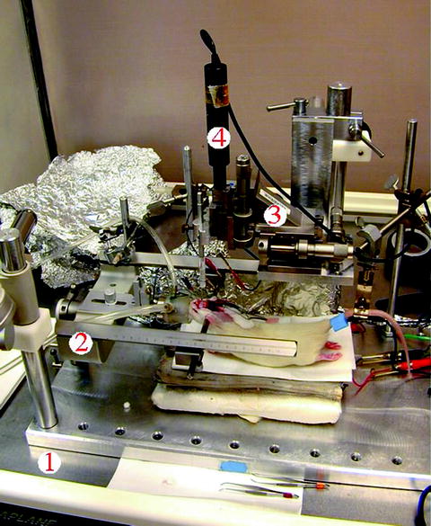
Fig. 2.
Other equipment for intracellular recording in vivo.
(b)
Metal cage.
(c)
Electrode puller:
We use Kopf 750 vertical electrode puller.
(f)
Heater:
We use bipolar temperature controller (TC-202, Medical System, Fig 1(6)) with a heating pad.
(g)
Soft paraffin wax:
Soft paraffin wax is used to cover the brain surface after placing the recording electrode into the recording area. surface soft wax protects the brain from desiccation and reduce the brain pulsation. Soft paraffin wax is prepared by mixing the solid paraffin prills (J.T. Baker) and mineral oil (Fisher Scientific, Hanover Park, IL) in proportion (start with 50 vs. 50%). The final product should be in the solid phase at room temperature (24°C) and in the liquid phase at ∼40°C. So we can pour the wax into the well to cover the brain without hurting the brain tissue due to the heat (Fig. 3).
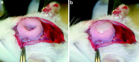
Fig. 3.
Photomicrograph showing the well before (a) and after (b) the soft wax is put above the recording site.
(h)
Anesthesia:
For general anesthesia, urethane (1.25 g/kg, i.p.) is used. Supplemental doses of ketamine and xylazine mixture (10 mg/kg, i.m.) are used once per hour as needed. If the possible side effects of ketamine on glutamate receptors are the concern, 1–2% isoflurane mixture with 33% oxygen and 66% nitrogen is a good agent for anesthesia. Another advantage of using isoflurane is that the animals recover from anesthesia minutes after turning off the isoflurane supply.
1.3 Procedures
1.
Preparing electrodes.
2.
Recording electrodes:
Preparation of recording electrode is critical for successful intracellular recording in vivo. Recording electrode is pulled from a Borosilicate glass tubing with filament (2.0 × 1.16 mm, 4″, A-M systems) with Kopf 750 vertical electrode puller. Carefully adjust the parameters of Heat 1, Solenoid current and Delay time to obtain an electrode with the smooth taper and shank. The most important part is to obtain a small tip with a diameter of 0.2–0.5 μm. Because it is difficult to measure the diameter, the measurement of electrode tip resistance is a good way to evaluate the size of the electrode tip. Normally, a resistance of 40–100 MΩ with the electrode solution of 2 M potassium acetate or 2 M potassium methylsulfate is a good electrode.
3.
Stimulus electrodes:
Stimulating electrodes are stainless steel insect pins (000, Carolina Biological Supply) insulated with epoxylite, except for 0.5–1 mm at the tip. They are placed in pairs separated by 0.5–0.75 mm with dental cement and connected for bipolar stimulation.
4.
Reference electrodes:
Silver wire (0.025″, A-M System) coated with silver chloride is used as reference electrode. The reference electrode is wrapped with cotton soaked with 0.9% sodium chloride and placed subcutaneously near the open skull. The reference electrode is connected to the ground by taping it tightly onto the ear bar of the stereotaxic frame.
5.
Animal preparation:
The animals are anesthetized with urethan (1.25 g/kg, i.p.) or 1–2% isoflurane, 33% O2, and 66% N2. The skull is opened to expose the cortex above the recording site and for placement of stimulus electrodes. A well is built with dental cement on the skull around the recording site for later putting the soft paraffin wax to cover the exposed brain. Then, the dura and pia are carefully opened to expose the cortex. The surface of the brain is covered with a piece of cotton soaked with saline to keep the moisture of the brain surface. To reduce brain pulsations, Cisternal drainage is performed by opening the posterior atlanto-occipital membrane and the animal is suspended by a clamp applied to the tail (see Fig. 2). Then, the wet cotton is removed from the brain surface and the recording electrode is placed into the surface of the cortex. The soft wax is poured into the well to cover the brain.
6.
Intracellular recording:
Before the recording, the electrode capacitance should be neutralized. The series resistance of the electrode should be compensated using bridge balance method. A 30-ms duration hyperpolarizing current pulse of 0.1–0.3 nA is delivered and the membrane potential deflection generated by the pulse is adjusted to baseline using the bridge balance knob of the amplifier. The electrode is advanced with 1–2-μm step using a motion controller (see Fig 2 (4)). A high-frequency buzz of 10 ms is used through the headstage preamplifier to facilitate the penetration of the cell membrane. When the electrode penetrates into the cell membrane, a sudden drop of membrane potential occurs, sometimes accompanying with a burst of action potentials. The electrode advancing should be stopped immediately and hyperpolarizing currents should be delivered to maintain the membrane potential at ∼−70 mV. The hyperpolarizing current should reduce very slowly to zero with the reseal of the cell membrane around the electrode. The resting membrane potential of the cell should be at ∼−60 mV without any current injection. The series resistance and the capacitance should be readjusted before collecting the electrophysiological data.
7.
Intracellular staining:
For intracellular staining, the recording electrode is filled with 3–5% neurobiotin (Vector Lab) in 2 M potassium acetate. At the end of the recording, depolarizing current pulses (2 Hz, 300-ms duration, 0.5–1.0 nA) are delivered for 10–30 min to inject the neurobiotin into the cell. In an experiment, more than one neuron could be recorded and stained. In order to match the electrophysiological data with the morphology of the neuron, it is essential to unequivocally identify the neurons after histological examination. We develop a chart to record the 3D parameters of the location of the recorded neurons (Fig. 4). In the chart, the numbers of the horizontal axis are the measurement from the midline of the skull and the numbers of the vertical axis are from the interaural line (9). First, write down the mediolateral and rostrocaudal parameters when placing the electrode into the recording site. After a successful intracellular staining, a note should be made for the depth of the neuron. The next recorded electrode should be placed at least 0.5 mm apart from the previous one. Based on these 3D locations, it is relatively easy to identify the neurons for which the intracellular recording and staining are performed.
Fig. 4.
Chart for the location of the recorded neurons. Circles 1 and 2 are examples of recorded neurons with the depth from the cortical surface in comments. DV dorsal–ventral.
8.
Histological procedures:
At the end of the experiment, the animal is given a large dose of anesthesia, perfused transcardially with 0.01 M phosphate-buffered saline (PBS) followed by 4% paraformaldehyde in the same buffer. The brain is removed and stored in fixative overnight. Coronal vibratome sections are cut at 50-μm thickness, incubated in 0.1% peroxidase-conjugated avidin-D (Vector Lab) in 0.01 M potassium PBS (KPBS, pH 7.4) with 0.5% Triton X-100 overnight at room temperature. After detection of peroxidase activity with 3′,3′-diaminobenzidine (DAB), sections are examined in KPBS. Each recovered neuron is identified with the recording chart (Fig. 4) and matched with the electrophysiological data. Those sections containing labeled neurons and stimulation sites are mounted on gelatin-coated slides and counterstained with cresyl violet for light microscopy. Figure 5 shows a neuron recovered after intracellular staining.
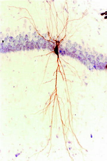
Fig. 5.
An example of CA1 neurons in hippocampus after intracellular staining. The section is counterstained with cresyl violet.
1.4 Limitations
Anesthesia effects: Intracellular recording is performed on animals under anesthesia and fixed on stereotaxic frames. The effects of anesthetics on neuronal activity and synaptic transmission should be taken into consideration with data interpretation. For example, ketamine has effects on NMDA receptor, which might have functional consequences on glutamate receptor-mediated synaptic transmission under physiological condition and on excitotoxic cell death in neurological disorders. Therefore, the data from intracellular recording should be integrated with results obtained from other techniques, such as recording from freely moving animals and behavior studies, to avoid misinterpretation.
Complex neuronal network effects: The advantage of in vivo recording is the preservation of the intact neuronal system. However, due to the complex neuronal circuit and the interconnections between neurons, the evoked postsynaptic potentials (PSPs) recorded by in vivo recordings are the combination of excitatory (EPSPs) and inhibitory PSPs (IPSPs). Sometimes, the weak IPSPs are masked by the strong EPSPs or vice versa. Therefore, the EPSPs or IPSPs evoked by a specific pathway should be carefully examined and confirmed before reaching the conclusions.
2 Patch-Clamp Recording on Brain Slices
2.1 Introduction
Brain slice preparation was developed in 1930s (10) and electrophysiological recording from brain slices has been conducted since 1960s (11). Introduction of patch-clamp recording technique in the mid 1970s revolutionized the field and moved the neuroscience research to a new level (12).
< div class='tao-gold-member'>
Only gold members can continue reading. Log In or Register to continue
Stay updated, free articles. Join our Telegram channel

Full access? Get Clinical Tree


