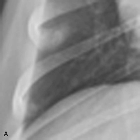
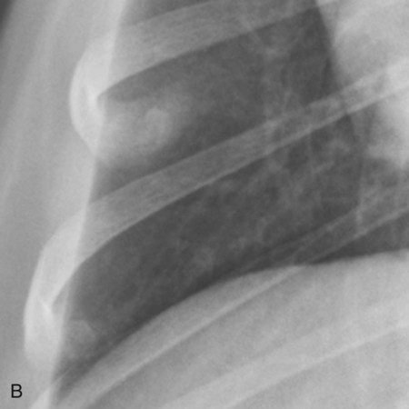
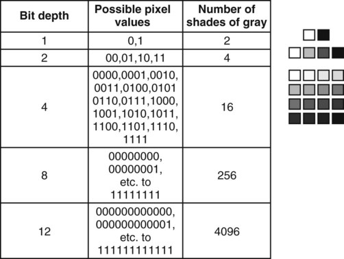
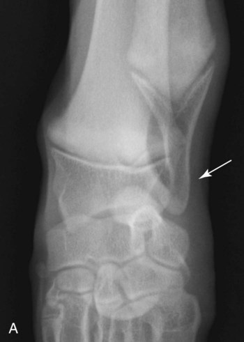
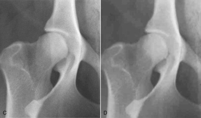
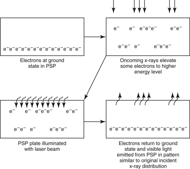
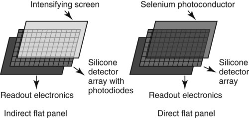
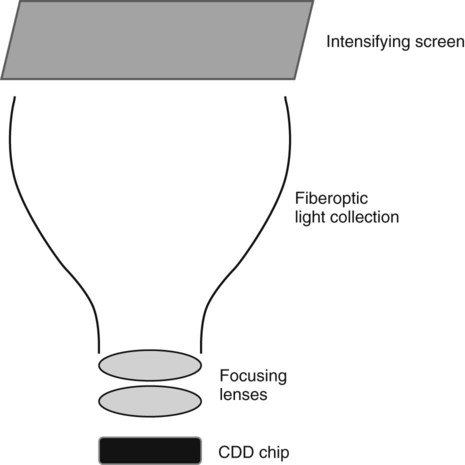
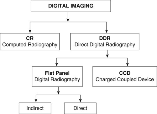
In diagnostic medical imaging, the computer file is a DICOM format; DICOM is an acronym for Digital Imaging and Communications in Medicine. A DICOM file is a computer file format of the same basic type as JPEG and TIFF files.1 In addition to the actual image information, however, each DICOM file has a header that contains other related information about the image, including the manufacturer of the device that generated the image; the date and time of image acquisition; patient demographic information; acquisition parameters; referrer, practitioner, and operator identifiers; and various other image parameters.1 The DICOM file format was derived mainly for consistency to ensure interconnectivity between imaging devices.2 Without interconnectivity, such as would occur if every vendor encoded the digital radiographic image into a proprietary file format, the convenience of having images in a digital format is reduced greatly. For example, without a standard DICOM file format, images acquired on a digital plate from vendor “A” could be viewed only on software provided by vendor “A.” This is a disadvantage because the purchaser might like the features of the hardware but not the features of the software. With the DICOM standard, images created on equipment from vendor “A” can be viewed on a variety of platforms, not only on those from vendor “A.” Compliance with formatting digital image files in DICOM format is voluntary. Most reputable vendors realize the advantages of total DICOM compliance, and the DICOM format has become the universal standard in medical imaging, across vendors, modalities, and computer operating systems. It is important that vendor adherence to the DICOM standard be verified before hardware is purchased, otherwise this tremendous flexibility in viewing and file transmission is lost. The DICOM standard provides for the transmission of medical images from one device to another, such as modality to server or server to workstation, using a network protocol that runs on top of the existing Internet standard protocol. DICOM images can also be transferred using browser-based technology, and this enhances image portability, particularly when accessing images beyond the local area network. The size of each pixel in a digital image determines the spatial resolution of the image; that is, how small of an object can be detected (Fig. 2-1). The hardware provided by the vendor determines the size of the pixel array in a digital radiographic image. In general, more pixels are better, but for any imaging system there is a point, at which more pixels do not result in a superior image. Although pixel size is important, there are many other hardware and technical factors that ultimately affect the “clinically useful” spatial resolution. Also, detailed later, software manipulation of the raw image file so as to optimize the displayed image is, within limits, more important than pixel density. As noted before, in medical digital images each pixel is assigned a shade of gray. The number of available gray shades for each pixel will influence the contrast of the image. If a pixel can have only a few gray shades, the image can only have a very short scale of contrast (high contrast) because there will be only black pixels, white pixels, and pixels of a few gray shades. If, conversely, there are many gray shade options for each pixel, the scale of contrast can be long. Computer files use binary notation to assign a gray shade to a pixel. In binary notation, the only digits used are 0 and 1. For grayscale assignment, a zero is assigned black, and a one is assigned white; combinations of zeros and ones can be used for various intermediate gray shades. If n equals the number of allowable number of zeroes and ones per pixel, then 2n is the number of combinations of zeroes and ones, and consequently the number of gray shades that are possible. The more combinations of zeroes and ones, the more gray shades there are possible in each pixel. The number of possible gray shades is referred to as the bit depth of the image (Fig. 2-2). Image file size and bit depth are directly related. Without the ability to assign multiple gray shades to each pixel, the image would have no diagnostic value (Fig. 2-3). In general, there are two main types of digital radiography acquisition hardware, computed radiography (CR) and direct digital radiography (DDR).3 As noted earlier, the conventional x-ray tube, x-ray table, and grid are used for both CR and DDR applications. The difference between analog and digital imaging is that the film cassette, used for analog imaging, is replaced with a digital recording device to record the distribution of x-rays transmitted through the patient. In CR systems the digital recording device is a cassette that contains a flexible imaging plate, and in DDR systems the digital recording device is a rigid imaging plate or imaging chip (no cassette). Charge-coupled device (CCD) systems, which are a special type of DDR, may require purchase of a new x-ray table because the hardware components are housed in the x-ray table, and it may not be possible to retrofit the new equipment into an existing x-ray table adequately. CR was the first digital radiographic system to come on the market. In CR, a cassette that appears outwardly similar to a film cassette is used. The CR cassette does not contain an intensifying screen or x-ray film but instead contains a flexible CR imaging plate coated with a photostimulable phosphor (PSP). In CR, the x-ray attenuation pattern of the patient is temporarily stored as a latent image within the PSP. The latent image is created by changes in electron energy bands that result from x-rays striking the PSP. The latent image is read out optically as photostimulated luminescence when the PSP plate is subsequently stimulated using a scanning laser (Fig. 2-4).4 Therefore, the CR plate must be processed in a plate reader following radiographic exposure. The processing steps in the CR radiography process are summarized as follows:5 • After exposure, the CR cassette is removed from the x-ray table and inserted into the reader. • The PSP plate is removed automatically from the CR cassette by the reader. • The PSP plate is illuminated in the reader by a laser. • Visible light is emitted from the PSP plate. • Emitted light strikes the photomultiplier tube where it is converted into electronic signal. • The electronic signal is digitized and stored as a digital file. • The PSP plate is exposed to bright white light to make sure all electrons are at ground state in preparation for the next exposure. • The PSP plate is returned to the cassette. • The cassette is ejected from the reader for use on the next patient. Indirect flat-panel detectors are termed indirect because they produce light as an intermediate step in image formation. An x-ray intensifying screen, identical in principle to those discussed in Chapter 1, is used to convert x-ray energy emerging from the patient into visible light.5,6 The intensifying screen is layered onto a panel containing an array of tiny photodiodes. Much as with the photostimulable phosphor found in the CR plate, the photodiodes convert light emitted from the intensifying screen into an electronic signal that is then read out by a thin-film transistor array and transformed into an electronic file (Fig. 2-5). To have good spatial resolution, the size of each detector element is very small, and a full-size imaging plate measuring approximately 43 cm × 43 cm may have a photodiode matrix of at least 2600 × 2600. Thus, an indirect flat-panel detector can have on the order of 6 to 7 million photodiodes or more. As can be imagined, the electronics needed to record and spatially localize the signal from each photodiode, or pixel, and to also incorporate the photodiode into each detector element is quite complicated. This contributes to the relatively high cost of flat-panel detectors compared with a film-screen cassette system. Indirect flat-panel detectors are commonly capable of a bit depth of 14, meaning there is a grayscale resolution of 16,384 gray shades per pixel.6 Most digital radiographic systems range in bit depth from 10 to 16 (1024 to 65,536 shades of gray). As the human eye can register only 50 to 100 simultaneous shades of gray, even with extreme manipulation of image contrast (postprocessing—see later), there is probably little benefit in generating images with more than 14- to 16-bit depth. In a direct flat-panel detector there is no light intermediary. Oncoming x-rays strike a photoconductor, typically composed of amorphous selenium, which has high efficiency x-ray absorption. Electrons liberated in the selenium layer by the oncoming x-ray beam are collected to form a charge. This charge is then read out directly by the thin-film transistor array, processed by the readout electronics and converted to an electronic file (see Fig. 2-5).5,6 As with indirect flat-panel detectors, there are millions of detectors in the array, and the pixel matrix is of comparable size, also with a bit depth of 14. Thus, the main difference between indirect and direct flat-panel detectors is the intermediate step of light production from the intensifying screen in indirect systems. As discussed in Chapter 1, there is some light diffusion within an x-ray intensifying screen. This light diffusion, which can potentially lead to blurring, is a purported disadvantage of indirect flat-panel detectors versus direct flat-panel detectors. However, with modern engineering techniques, and the structure of the crystals in the intensifying screen, the amount of light diffusion that actually occurs in the intensifying screen of the indirect flat-panel detector is minimal and not clinically significant. For all practical purposes, the functionality of modern-day indirect and direct flat-panel detectors is comparable. CCD chips are relatively small compared with a flat-panel detector, being only a few centimeters on each side, compared with up to 43 cm for flat-panel detectors. Although small, there may be millions of pixel elements on the surface of a CCD chip. The CCD chip is sensitive to visible light, not x-rays; this is the basis for their use in camcorders and digital cameras. Thus, for radiography based on CCD technology, a light intermediary is necessary, and this, as in indirect flat-panel detectors, is accomplished by integration of a relatively standard x-ray intensifying screen between the patient and CCD chip. When the CCD chip is exposed to light that has been focused from the intensifying screen, the pixels in the CCD chip accumulate electronic charge, which is read out and converted to an electronic file.5 The geometry of the CCD system deserves special consideration. Given the small size of the CCD chip, the light output from the intensifying screen needs to be focused onto the chip, whereas in an indirect flat-panel detector the intensifying screen is layered directly onto the detector. Focusing of light from the intensifying screen onto the CCD chip is usually accomplished by integration of fiberoptic light collection and a focusing lens between the intensifying screen and CCD chip (Fig. 2-6). Thus, the quality of the image depends more on the quality of the light collection and focusing than on the quality of the CCD chip. Also, there is some loss of light and potentially much light distortion between the intensifying screen and CCD chip, leading to image degradation. In general, CCD radiography in humans has been reserved for situations where the part being imaged is relatively small (e.g., dental radiography and mammography) and there is less need for light focusing. In veterinary medicine, the parts being radiographed are larger and requirements for focusing more stringent; this can lead to poorer images than obtained with flat-panel detectors, and image quality from CCD systems is considered by many to be inferior to both flat-panel and CR systems. Also, the distance required for collecting and focusing the light from the intensifying screen means that the physical device is quite large compared with a flat-panel detector. Because a result, CCD detectors are housed within the x-ray table. As this cannot be done easily in a retrofit manner, purchase of a new x-ray machine may be necessary if CCD technology is chosen. The size of the device also limits portability, and there is a requirement for a constant vertical relationship between the x-ray tube and CCD camera; both of these factors eliminate the possibility of using CCD technology for portable imaging. CCD systems are typically less expensive than flat-panel imaging systems or high-quality CR systems, but image quality is usually inferior. A summary of the various hardware options is shown in Figure 2-7.
Digital Radiographic Imaging
The Digital Image File
The Components of a Digital Image
Digital Radiography Acquisition Hardware
Computed Radiography
Direct Digital Radiography
Indirect Flat-Panel Detectors
Direct Flat-Panel Detectors
Charged-Coupled Device
Veterian Key
Fastest Veterinary Medicine Insight Engine