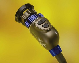
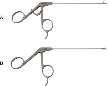
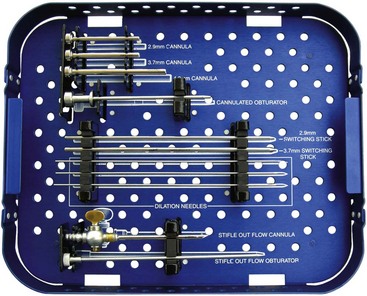
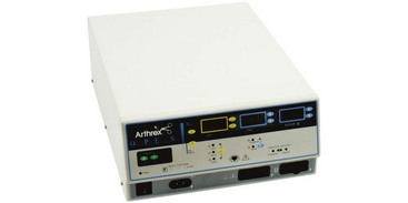
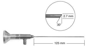
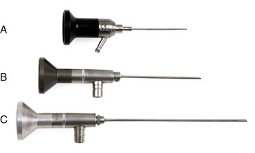
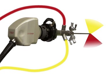
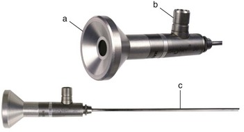
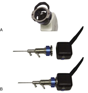
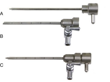
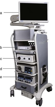
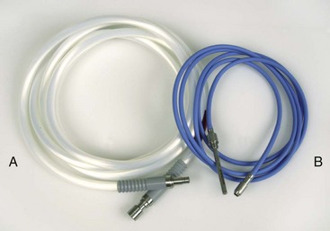
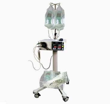
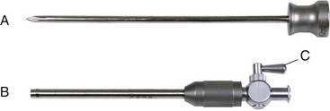
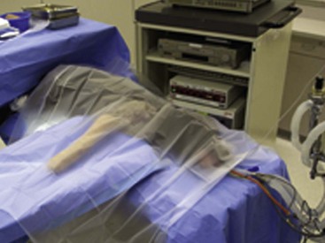
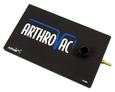
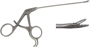
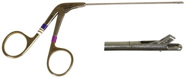
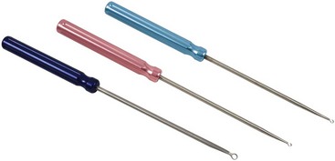
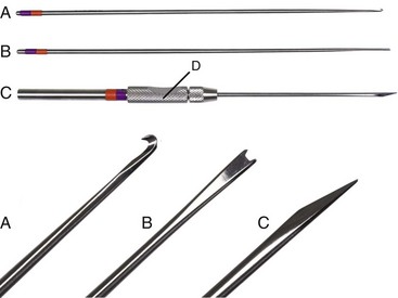
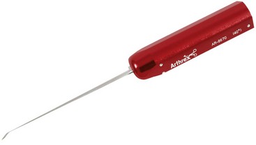
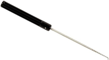
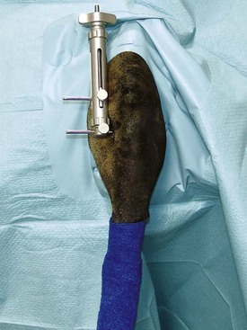
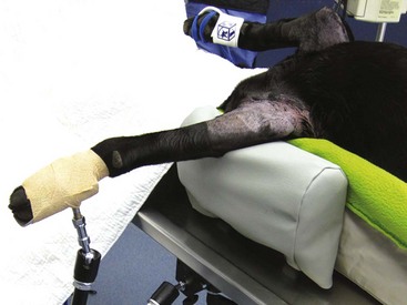
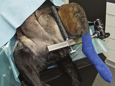
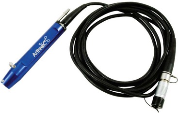
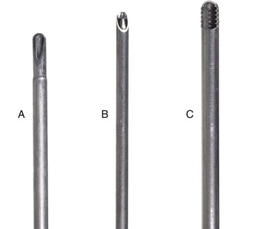
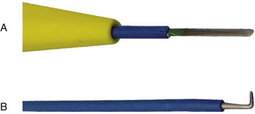
Chapter 71 Arthroscopy is defined as endoscopy of a joint. It is performed with a rigid endoscope, which in small animals is often of a diameter between 1.9 and 2.7 mm. The first use of arthroscopy in small animals was reported by Siemering, who described arthroscopic exploration of the stifle joint in 1978.33 Contemporary small animal arthroscopy is performed most commonly in the dog and rarely in the cat, with the most frequently explored joints being the shoulder, elbow, and stifle. Techniques for arthroscopy of the hip joint, carpus, and tarsus are well described but are less commonly used.2 As with any medical advancement, this technique has both advantages and disadvantages. Documented advantages of small animal arthroscopy include decreased patient morbidity, more rapid recovery, decreased complication rates, improved functional outcomes, decreased anesthesia and surgery times, decreased hospitalization time, and enhanced client satisfaction.11,16,27 Suggested disadvantages include the relatively high level of skill required, the high cost of equipment, and potentially increased costs to the client. Arthroscopes are commonly described by three measurements: telescope diameter, distal lens angle (viewing angle), and working length (Figure 71-1). The telescope diameter is the outer diameter of the tubular portion of the arthroscope without the accompanying cannula. Arthroscope diameters commonly used in small animal arthroscopy include 1.9 mm, 2.3 mm, and 2.7 mm (Figure 71-2). Arthroscopes with smaller telescope diameter minimize joint trauma and are more easily manipulated in joints that are highly congruent and have limited joint space, such as the canine elbow and hock, than are arthroscopes with larger telescope diameter. Arthroscopes with larger telescope diameter permit a larger field of view and offer greater resistance to bending and, therefore, greater durability. Lens angle is the angle between the center of the viewing range and the axis of the telescope (see Figure 71-1). The angles most commonly available in arthroscopes are 0 degrees, 30 degrees, and 70 degrees. Beveling the lens of the arthroscope increases the field of view and enables examination of a larger area of the joint simply by rotating the arthroscope. The 30 degree arthroscope is the most common type used in canine arthroscopy. Rotation of a 30 degree arthroscope allows the equivalent of a 60 degree field of view (Figure 71-3). Working length, which is the overall length of the shaft of the telescope, is usually designated as “short” or “long.” Short arthroscopes have a working length of approximately 8.5 cm; long arthroscopes have a working length of approximately 13 cm. Short arthroscopes provide adequate length for most small animal arthroscopy with the possible exception of the canine hip joint. The ocular (or near) end of the arthroscope includes an eyepiece or camera mount, a light source post, and a cannula interlock (Figure 71-4). The connection between the arthroscope and the camera is available in two styles. The most common type uses a spring-loaded clip that enables quick attachment of the arthroscope to the camera. The other type is a direct-coupling, or “glass-on-glass,” system, in which the arthroscope is coupled to the camera using a threaded interface (Figure 71-5). The internal designs of most arthroscopes are similar, and only modest differences have been noted in the quality of the optics; however, individual surgeons often develop preferences based on arthroscope size, length, and design. The arthroscope is inserted into the joint through a cannula that serves multiple functions, including maintenance of the arthroscope portal (an incision through the skin and periarticular soft tissues, including joint capsule, that allows access to the joint), protection of the arthroscope, and ingress of fluid (Figure 71-6). An arthroscope should never be inserted into a joint without a cannula because the lens may be damaged and the telescope bent during insertion. The cannula is inserted first to establish a portal into the joint. The cannula is a steel tube that is slightly larger than the arthroscope. It permits fluid to run into the joint in the space between the telescope and the cannula. The far end of the cannula is beveled to match the angle of the arthroscope. The near end of the cannula has an interlock mechanism that allows connection to the arthroscope and attachment of a fluid line. Cannula interlock designs vary between manufacturers, with designs ranging from simple J-locks to more complex spring-lock mechanisms. Cannulas are designed to match a specific arthroscope and usually are not interchangeable. The image from the arthroscope is projected onto a monitor with an endoscopic video camera system (Figure 71-7). This camera system includes a control unit and a camera head. The camera head includes an electronic chip, a clip or thread that attaches to the ocular end of the arthroscope, and a cable that connects this assembly to the control box. The electronic chip is a semiconductor that converts the image to an electronic signal. Older camera systems convert images from digital to analogue; newer cameras use a purely digital system. Virtually all arthroscopic cameras currently sold use three chips, although used single-chip cameras may still be found. The most expensive and advanced cameras are high-definition (HD) three-chip cameras rather than standard definition (SD). High-definition cameras produce more pixel lines per screen and therefore a sharper image. Most camera heads fit most arthroscopic eyepieces using the clip mount system, although it is advisable to ensure compatibility before purchasing components from different manufacturers. Many camera heads have controls that permit white balance, image capture, or zoom. The end of the cable that plugs into the control box has a cap that protects the connecting pins or the card edge connector from damage during sterilization and handling. During an arthroscopic procedure, the surgeon should not remove the cap because the interior is not sterilized. Instead, a technician removes the cap after this end of the cable is passed off of the table. The control box (Figure 71-8) relays the image to the monitor and is specific for the camera. Sterilization of the camera may be achieved by EtO, peracetic acid (Steris Corporation), or hydrogen peroxide gas plasma (Sterrad System; Advanced Sterilization Products), or in some cases by steam autoclaving, if the camera is designed and rated for steam. Activated glutaraldehyde (CyDex Pharmaceuticals, Inc., Lenexa, KS) is a popular method of sterilization because of its rapid effect and limited damage to the equipment; however, glutaraldehyde must be thoroughly rinsed from the equipment to avoid chemical damage to the joint. Figure 71-7 Arthroscopic three-chip camera with controls for zoom, white balance, and image capture. The arthroscopic image is viewed on a standard analogue color monitor. Monitors for arthroscopy should have high horizontal resolution and should be of adequate size for ease of viewing. Flat screen monitors are used most commonly. The quality and resolution of the monitor should fit those of the camera to avoid loss of image quality. For example, image quality will be lost if an high-definition camera is used with an standard definition monitor or recorder (see Figure 71-8). Light sources provide illumination within the joint. The light source box contains the lamp and intensity regulators. Halogen and xenon arc light sources are commonly used. Xenon lamps are most common because they provide increased light intensity and higher color temperature and, therefore, greater visual clarity and color rendition. Xenon lamps may fail suddenly (versus gradually, or without warning); therefore it is important to have a spare bulb available. Halide lights produce a more yellow color and dim gradually, which may be a disadvantage if the loss of intensity is not noticed by the operator. Halide bulbs are also less cost-effective than Xenon bulbs. Most light sources include automatic intensity control through feedback from the camera video output system. Light from the light source is conveyed to the arthroscope through a fiberoptic cable that attaches to the light post on the arthroscope (Figure 71-9). The connection on the light source may be specific to the manufacturer; however, many light sources have a spring-release connection that permits use with almost any fiberoptic light cable. The type of connection between the light cable and the arthroscope varies with the manufacturer and the size of the arthroscope. Documentation of arthroscopic procedures provides a permanent visual record that allows historical archiving of arthroscopic findings and therapy, and facilitates client and professional communication. Most contemporary arthroscopy systems include a means of digitally recording still images and video (see Figure 71-8). Numerous systems are available, and the selection should be made on the basis of needs, application, and cost. Arthroscopic printers are available and produce high-quality prints, but their use is often impractical. Numerous studies have evaluated the effects of fluid type and temperature on cartilage and patients undergoing arthroscopy.1,7,29,39 Saline and lactated Ringer’s solution both have been used for arthroscopic irrigation, and several studies have shown no difference between the effects of these fluids on cartilage metabolism; however, other studies have suggested that lactated Ringer’s solution may be more physiologic for cartilage and may have fewer negative effects on the meniscus than saline.32 Cold irrigation fluid may aid in achieving hemostasis and in minimizing thermal damage if radiofrequency or electrocautery is used; however, cold arthroscopic irrigation fluid has been shown to affect patient core temperature in human arthroscopy.5,8 Irrigation systems must deliver fluid with sufficient pressure to distend the joint and maintain flow without increasing the extravasation of fluid into periarticular soft tissues. Fluid enters the joint through the space between the telescope and the cannula. In some cases, a separate inflow cannula may be used to introduce large volumes of fluid. Indications for the use of a separate inflow cannula include lavage of a blood-filled or septic joint, where large-volume lavage is particularly beneficial to aid in removing debris. With any irrigation system, fluid usually must be pushed into the joint under pressure to achieve adequate flow. The intra-articular pressure necessary for arthroscopy varies, depending on the joint and the purpose of arthroscopy. However, most studies suggest that 60 mm Hg is a reasonable starting pressure.35 Excessive pressure can cause soft tissue injury and extravasation into periarticular tissues. No studies are investigating appropriate irrigation fluid pressures for canine arthroscopy. Fluid may be pressurized by gravity flow or with an electric fluid pump. Both systems have advantages, and selection often depends on the joint being operated on, as well as surgeon preference. Gravity flow is seen in administration of fluid directly from a fluid bag to the cannula with a simple administration set. The diameter of the administration set tubing determines the fluid flow rate. Large-diameter tubing allows a higher flow rate and is available specifically for arthroscopy. The rate of fluid flow may be increased by placing the fluid bag in a pressure bag or by elevating the fluid bag. Elevation of fluid bags to as high as 8 or 9 feet is recommended to achieve adequate hydrostatic pressure.2 Use of a 3 or 5 L bag may improve pressure and decrease the need for a technician to replace fluid bags or reinflate pressure bags. Also, Y-adaptors permit multiple bags to be connected at the beginning of the surgical procedure. Advantages of gravity flow include the relative simplicity of the system, low cost, and safety against overpressurization. Gravity systems are easy for the surgeon and technician to learn and to use. In addition, they are easy to maintain and do not require additional space in the operating room or on the arthroscopy tower. Most small animal arthroscopy procedures can be accomplished with gravity flow. Fluid pumps permit selection of both fluid flow rate and fluid pressure (Figure 71-10). Most use pressure priority, which means that selected pressure in the joint will be maintained, and when the pressure drops below this level, fluid will be pumped into the joint to maintain the selected intra-articular pressure. Fluid pumps are superior to gravity in maintaining pressure when suction or shaver systems are in use, as use of these systems can result in the rapid removal of fluid, a sudden decrease in intra-articular pressure, and collapse of the joint. Disadvantages of fluid pumps include their initial cost and the cost of administration sets, the moderate complexity of tube setup, and the space requirements. Adequate outflow of fluid, or egress, must be established to maintain appropriate fluid flow through the joint during arthroscopy. Egress may be achieved by permitting outflow through an instrument portal or by inserting a specific egress instrument. Few disadvantages are seen in permitting egress only through an instrument portal, as long as it provides adequate flow. This technique does require establishing the instrument portal early in the procedure, regardless of whether or not instruments will be used. Alternatively, a specific egress tool may be inserted into the joint. In smaller joints, this is often a hypodermic needle; in larger joints, it is often a multifenestrated cannula (Figure 71-11). One advantage of an egress tool over use of the instrument portal is that a needle or cannula can be blocked intentionally to pressurize the joint, if needed. A second advantage is that tubing may be attached to the end of the needle or cannula to scavenge fluid, although this may inadvertently establish a siphon that can alter fluid flow in the joint and introduce air bubbles. The disadvantage of use of an egress needle or cannula is the potential for additional iatrogenic damage to the joint, along with the need for additional instrumentation in and around the joint. In most cases, fluid is not scavenged from the egress portal but is allowed to flow onto the operating room floor. The patient may be protected from moisture and subsequent secondary hypothermia with the use of clear plastic sterile adhesive draping systems (e.g., SteriDrape 3M, St Paul, MN) (Figure 71-12). Fluid can be removed from the floor with the use of commercially available floor suction devices (Figure 71-13). Grasping forceps are available as locking and nonlocking types (Figure 71-14). Nonlocking types include standard alligator forceps and those designed specifically for arthroscopic use. Most grasping forceps designed for arthroscopic use have an enclosed operating mechanism that avoids interference between the mechanism and surrounding tissues. Figure 71-14 Locking (A) and nonlocking (B) arthroscopic grasping forceps. (Courtesy Arthrex Vet Systems, Naples, FL.) Graspers vary in size and length, and selection depends on the joint, the specific procedure being performed, and the preference of the surgeon. For most small animal applications, pointed forceps without teeth are recommended (Figure 71-15). Locking forceps are advantageous in many arthroscopic procedures involving removal of bone chips or cartilage flaps. Many forceps designs are available in long and short lengths. Again, selection is based primarily on surgeon preference, although a shorter working length is recommended for smaller joints. Biting, or punch, forceps are used to biopsy or debride soft tissues (Figure 71-16). Punch forceps have a sharp, hollow lower anvil and an upper punch that is used to remove small pieces of soft tissue, including synovium and meniscus. Variations in design include straight and side biting, as well as differences in diameter and length. A small- or medium-diameter straight punch forceps is useful in small animal arthroscopy for debriding synovium that is obscuring the view, for obtaining a synovial biopsy specimen, and for debriding a meniscal injury. Small-diameter curettes are critical in small joint arthroscopy. These instruments are used to elevate bone fragments and to debride cartilage and bone. A small (5-0) surgical curette or arthroscopic curette is appropriate in most situations (Figure 71-17). Arthroscopic knives are useful in small animal arthroscopy for treating meniscal injury, performing tenodesis, and cutting soft tissue attachments to bony fragments. Knives may be straight, curved, or hooked; the choice depends on the procedure being performed. Specific designs of arthroscopic knives include meniscal and banana knives (Figure 71-18). Microfracture of the subchondral bone bed is routinely performed with angled awls or micropicks and a mallet. Micropicks may be straight or angled (Figure 71-19). Most probes are of a right-angle design with a tip that is approximately 3 mm long (Figure 71-20). Probes are used to palpate surfaces and manipulate tissues within the joint. In small animal arthroscopy, right-angle probes are used to palpate articular cartilage to detect pathology and to manipulate cartilage flaps, meniscal injuries, and bone fragments. Most probes have measurement markers that aid in reporting and imaging the size of lesions. Arthroscopic instruments may be inserted into the joint through a portal with or without a cannula (Figure 71-21). The major advantage of working through a cannula is the ease of instrument insertion. Without a cannula, it may be difficult to switch instruments and identify the portal, particularly if the portal was poorly made. Repeated attempts to insert an instrument through a poorly defined portal can lead to soft tissue trauma and fluid extravasation. The major disadvantage of using a cannula is that some instruments may be too large to permit insertion through the cannula. No general consensus has been reached on the use of cannulas in small animal arthroscopy, although anecdotally it appears that most surgeons do not routinely use them. Instrument cannulas are available in numerous diameters and lengths. For small animal arthroscopy, cannulas with an inner diameter of 2.3 to 3.5 mm and a length of 4 to 5 cm are most appropriate. Most cannulas come with both sharp (trocar) and blunt obturators. The blunt obturator should be used to minimize iatrogenic trauma during insertion of the cannula. Figure 71-21 Canine arthroscopic cannula and switching stick set. (Courtesy Arthrex Vet Systems, Naples, FL.) The use of instruments to distract the stifle joint has been described to aid viewing of the caudal horns of the menisci. A narrow Hohmann retractor or an angled micropick can be used intra-articularly to lever the proximal tibia cranially, improving the view of the caudal portion of the joint. An external distraction device using transcortical pins has been reported to achieve stifle joint distraction (Figure 71-22).6,14 Limb-positioning devices are commonly used in human arthroscopy and aid in providing accurate and stable limb positioning, while minimizing the number of individuals in the operating room. Limb-positioning devices for canine arthroscopy have been described for the stifle, elbow, shoulder, and hip (Figures 71-23 and 71-24).31 Stifle and elbow positioners are manufactured from a photographic clamp and arm device (Bogen Magic Arm and Super Clamp, Ramsey, NJ) and custom manufactured braces. Power shavers are designed to rapidly debride soft and hard tissues (Figure 71-25). Power shavers include a control box, a handpiece, and a shaver tip. Most shavers permit the operator to vary both the speed and the direction of the instrument, and options include forward, reverse, and oscillation. Speed control is important because different tissues require different approaches. Controls may be located on a foot pedal or on the handpiece. The handpiece connects the shaver to the control box (see Figure 71-8) and to suction. A suction regulator may be found on the handpiece as well. Suction improves the function of the shaver by pulling soft tissues into the cutting blade and removing debris from the joint. The handpiece is supplied by an electrical cord that has a capped connector that inserts into the control box. Shaver tips are available in numerous styles that are designed for soft tissue or hard tissue debridement (Figure 71-26). Soft tissue shavers include guarded sharp cutters and aggressive cutters. Sharp cutters have a simple sharp-edged cup, whereas aggressive cutters have a toothed cup. The toothed cup is more useful for debridement of fat or synovium in small joints. Most shavers have several options for operation, including a forward and a reverse direction, oscillation, and variable speed. When an aggressive cutter is used to debride the fat pad of the stifle joint, suction is applied and the shaver is operated in oscillation to optimize soft tissue debridement. Operation of the shaver at higher speeds limits the amount of tissue that can be drawn into the blade. Shaver tips used for debridement of bone include round and oval guarded burrs. Shaver tips are two-piece units that are separated for cleaning. Electrocautery and radiofrequency are used to generate heat for cauterization of vessels, debridement of tissues, or shrinkage of collagen (Figure 71-27). Electrosurgical tips specifically designed for underwater arthroscopic application are available for use with standard electrocautery generators (Figure 71-28). These instruments may be used for cautery of small vessels, and special tips are designed to cut soft tissues. Extreme caution must be taken during the use of electrocautery, as the heat generated can easily and rapidly damage ligaments, cartilage, and arthroscopes.18,19 Figure 71-27 Combined arthroscopic electrocautery and radiofrequency unit. (Courtesy Arthrex Vet Systems, Naples, FL.) The effects of radiofrequency on shrinkage and tissue strength depend in part on the temperature of the probe. Optimal temperatures range from 65° to 75° C. Higher temperatures cause greater weakening of tissues. Collagen and tissues undergoing shrinkage are weaker than normal for 6 to 12 weeks after the procedure. In addition, it is not known how long shrinkage of treated tissues persists. Although shrinkage by as much as 50% can be achieved experimentally, clinical shrinkage normally ranges from 15% to 25%. In addition to causing shrinkage, a radiofrequency unit may be used to ablate tissues, including proliferative synovium, torn or damaged meniscus, and partial-thickness cartilage lesions.18,19 The use of radiofrequency probes for management of shoulder joint instability has been reported in the dog.24 Current use of radiofrequency equipment in small animal arthroscopy appears to be limited owing to the severe damage that may be caused to cartilage and limited studies demonstrating the long-term efficacy of these techniques. Specific selection of an anesthetic protocol (see Chapter 24) for a patient undergoing arthroscopy is dependent on the age and medical status of the patient, as well as on the joint to be operated. A majority of patients undergoing arthroscopy are young or middle aged and otherwise healthy. Preanesthetics routinely include a sedative (acepromazine, valium) and an analgesic (opiates and/or nonsteroidal antiinflammatory drugs [NSAIDs]). Induction agents may include propofol or etomidate. Following induction, additional analgesia for hindlimb procedures can be provided with epidural administration of an opiate (preservative-free morphine), a local anesthetic, or both. Many procedures may be done on an outpatient basis; therefore short-acting inhalant anesthetics such as sevoflurane may be particularly appropriate. Postoperative analgesia may include additional opiates during hospitalization, with NSAIDs, tramadol, or both continued as necessary once the patient is discharged from the hospital. Proper joint positioning and distraction are critical to the success of arthroscopy and minimization of iatrogenic joint trauma. Positioning and distraction may be achieved with the aid of an assistant or with the use of positioning devices,31 which have known advantages and disadvantages. Devices occupy less space and represent a lower long-term cost; in addition, devices do not fatigue or move inadvertently; however, positioning devices do not allow rapid changes in joint distraction or angle. Positioning and distraction vary with the individual joint and are discussed in detail in specific joint sections of this text. Positioning of the equipment and in particular the monitor should be done in such a way that the surgeon can easily see the monitor at all times.
Arthroscopy
Equipment
Arthroscope
Cannula
Camera
Monitor
Light Source
Imaging
Irrigation
Egress Systems
Hand Instruments
Instrument Cannulas
Joint Distractors
Limb Positioners
Power Hand Tools
Electrocautery and Radiofrequency Devices
Basic Techniques of Small Animal Arthroscopy
Patient Preparation
![]()
Stay updated, free articles. Join our Telegram channel

Full access? Get Clinical Tree


